FAQ 004165 EN
How is it possible to consider the real cross-section geometry of member elements in RWIND Simulation?
Answer
The "Simulate and Generate Wind Loads" interface application allows you to exchange member, surface, and solid elements in RFEM, and member elements in RSTAB.
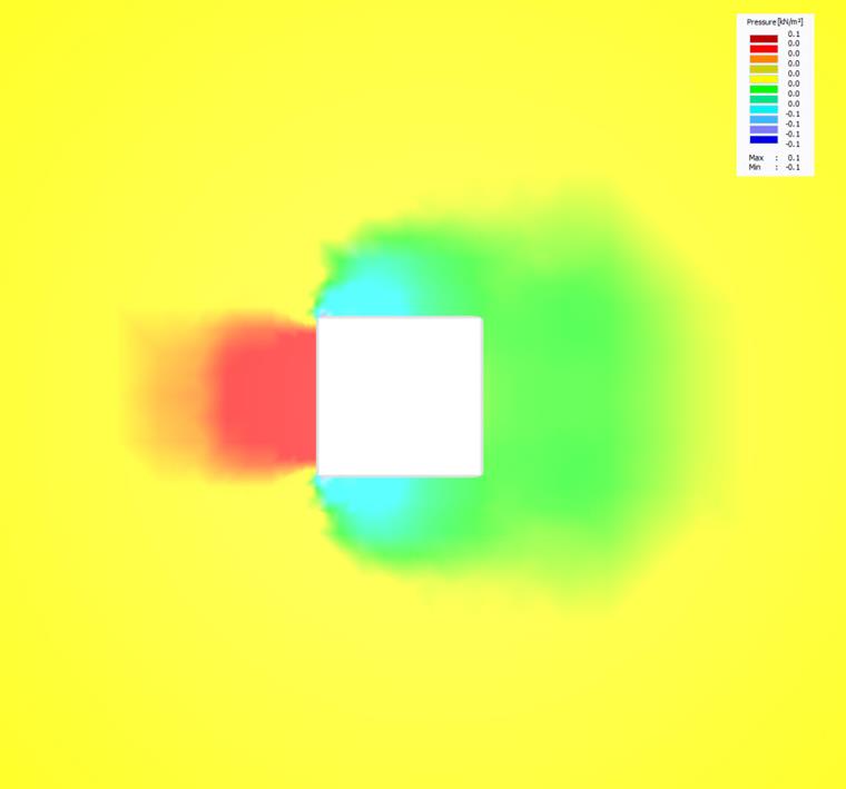
To avoid too fine mesh and thus too long calculation time, the program simulates all members with a rectangular cross-section by default. In this case, the size of the rectangular cross-section is selected in such a way that it barely includes the real cross-section geometry.
Figure 02 - Pressure Distribution Around Simplified (Optimized) Cross-Section Geometry
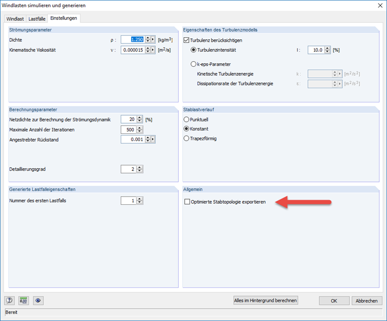
By deactivating the "Export optimized member topology" option, you can avoid this additional optimization of the model and allow consideration of the real cross-section geometry within the existing cross-section settings.
Figure 01 - Pressure Distribution Around Real Cross-Section Geometry
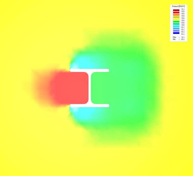
If the exact display of the cross-section geometry requires more than 1,000,000 elements, the interface automatically switches to the simplified rectangular cross-section display.
Keywords
Cross-section shape Wind tunnel Topology Member cross-section
Downloads
Contact us
Did you find your question?
If not, contact us via our free e-mail, chat, or forum support, or send us your question via the online form.
Recommended Events
Timber Beam and Surface Structures | Part 1: Modeling, Load Input, Combinatorics
Webinar 4 May 2021 2:00 PM - 3:00 PM CEST
Eurocode 3 | Steel structures according to DIN EN 1993-1-1
Online Training 6 May 2021 8:30 AM - 12:30 PM CEST
Eurocode 2 | Concrete structures according to DIN EN 1992-1-1
Online Training 12 May 2021 8:30 AM - 12:30 PM CEST
Eurocode 5 | Timber structures according to DIN EN 1995-1-1
Online Training 20 May 2021 8:30 AM - 12:30 PM CEST
RFEM | Structural dynamics and earthquake design according to EC 8
Online Training 2 June 2021 8:30 AM - 12:30 PM CEST
Stability Design in Steel Construction with RFEM and RSTAB
Webinar 1 December 2020 2:00 PM - 2:45 PM CET
Videos
Models to Download
Knowledge Base Articles

New
CSA S16:19 Stability Considerations and the New Annex O.2
Structure stability is not a new phenomenon when referring to steel design. The Canadian steel design standard CSA S16 and the most recent 2019 release is no exception.
Screenshots
Product Features Articles

SHAPE-THIN determines the effective cross-sections according to EN 1993-1-3 and EN 1993-1-5 for cold-formed sections. You can optionally check the geometric conditions for the applicability of the standard specified in EN 1993‑1‑3, Section 5.2.
The effects of local plate buckling are considered according to the method of reduced widths and the possible buckling of stiffeners (instability) is considered for stiffened sections according to EN 1993-1-3, Section 5.5.
As an option, you can perform an iterative calculation to optimize the effective cross-section.
You can display the effective cross-sections graphically.
Read more about designing cold-formed sections with SHAPE-THIN and RF-/STEEL Cold-Formed Sections in this technical article: Design of a Thin-Walled, Cold-Formed C-Section According to EN 1993-1-3.
Frequently Asked Questions (FAQ)
-
Why are my steel members not being designed for stability in RF-STEEL AISC?
- My section is classified as Class 4 and non-designable in RF-/STEEL CSA. However, my manual calculation shows a different class. Why the difference?
- I have defined temperature loads, strain loads, or a precamber. As soon as I modify stiffnesses, the deformations are no longer plausible.
- Can the properties, such as B. the cross -section or the surface thickness as well as the material of a surface of an existing element for a new element?
- I am trying to manually check the deformations from the CRANEWAY add-on module. However, I obtain great deviations. How to explain the differences?
- What should be considered when using a failure of columns under tension in the RF‑/DYNAM Pro – Equivalent Loads add-on module?
- Why is there no stability analysis displayed in the results despite the activation of the stability analysis in RF‑/STEEL EC3?
- How can I model and design a crane runway girder with Dlubal Software?
- Is it possible to set user-defined values when viewing solid stress results?
- Why do I get large differences for the design of a longitudinally stiffened buckling panel in comparison with the German and Austrian National Annex?
Customer Projects
Associated Products
Stand-Alone Program
Stand-alone program for numerical simulations of wind flow around buildings or any other objects. The generated wind loads acting on these objects can be imported into RFEM / RSTAB programs for static and dynamic analysis.
2,690.00 USD