Answer:
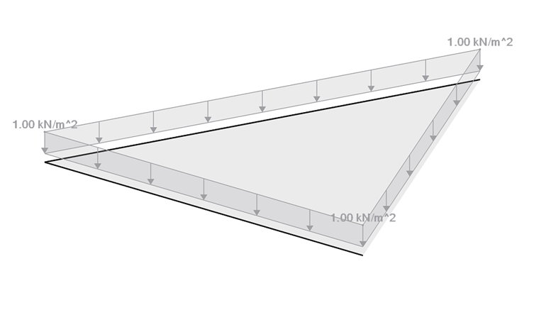
The structural system shown in Image 01 is loaded using the load generator.
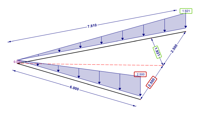
The result is shown in Image 02. Due to the different member lengths, the load magnitudes resulting on both beams are not the same. Image 02 also shows the graphical load distribution. The perpendicular connection of the members to the bisector is to be understood as the load application length. In both cases, the length is exactly the same.
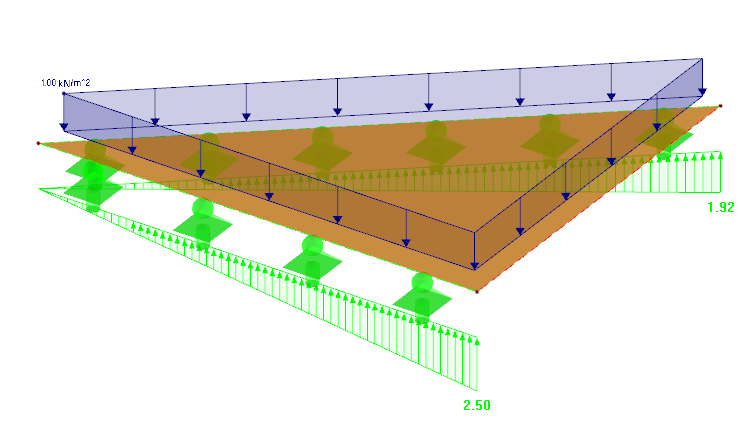
Image 03 also shows a check by means of a surface system. These are also consistent with the member model.