100 Results
View Results:
Sort by:

Question
Is it possible to reduce dynamic coefficients when using DIN EN 1993‑6?
Question
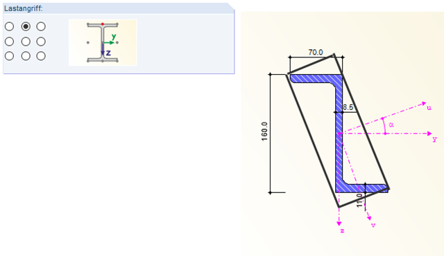
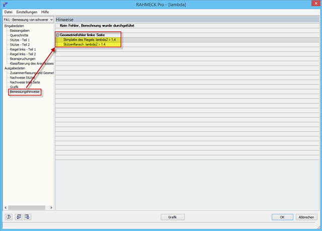
What does the design information mean:
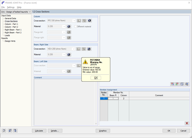
Geometry error left side:
End plate of the girder: Lambda2 >1.4
Column flange: Lambda2 >1.4
I cannot find an explanation in the manual or online.
Question
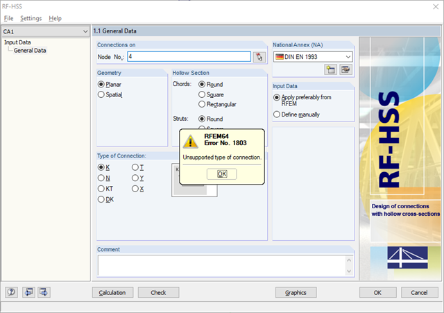
Why it is not possible to design a biaxial bending with the RF‑/JOINTS add-on module?
Question
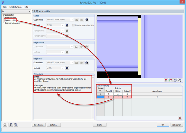
An attempt to design several connection nodes with the same geometry fails. According to the message, the connection geometry is different.
Question
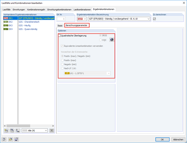
How do I superimpose generated equivalent loads from the seismic analysis?
Question
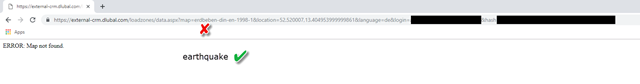
Why does the web service show "ERROR: Map not found."?
Question
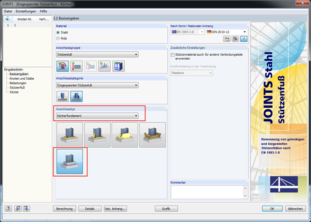
Do you have a program for designing columns restrained in concrete? It is not about the design of the bucket, but about the required embedment depth, the provided concrete stress, the check of the shear stress in the column, and so on.
Question
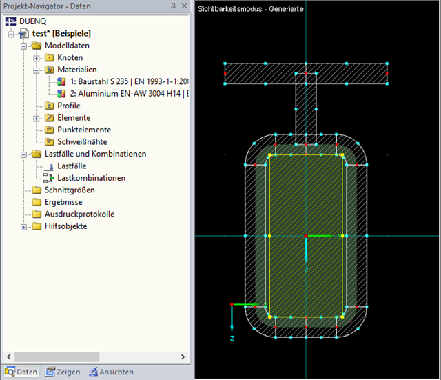
Is it possible to integrate several cross-sections into different materials when performing a flexural buckling analysis, or how can I apply several cross-sections to each other?
Question
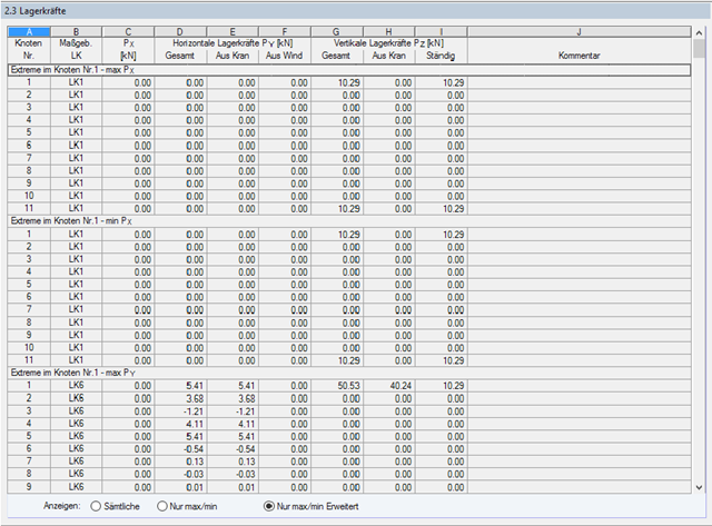
For a calculation, I activated the "Detailed Calculation" option. Have the support loads already been specified with the reduced dynamic coefficient for the design of the substructure?
Question
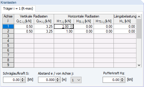
What is the meaning of the abbreviations for the crane loads in the CRANEWAY add-on module?
Question
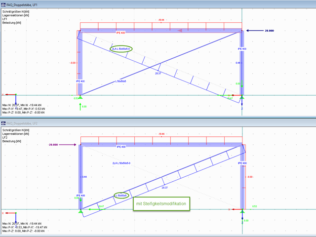
I used double members for the member input. Do I have to consider anything else, or is it better to enter a member with double cross-section properties?
Steel Bracket
I have to dimension a wall bracket as a steel brackets that I have modeled as surface components in RFEM 5. Which add-on module can I use to design it?
Question
I would like to design banisters, so I have created a set of members for this. The cross-section is a hollow section. Can the stability analysis be carried out on the entire structure, or do I have to convert it into an equivalent member design with the specification of all supports in STEEL EC3?
Question
Are the models and presentations from Info Day 2019 freely available, and can you send them to me?