The structural analysis software RFEM 6 is the basis of a modular software system. The main program RFEM 6 is used to define structures, materials, and loads of planar and spatial structural systems consisting of plates, walls, shells, and members. The program also allows you to create combined structures as well as to model solid and contact elements.
RSTAB 9 is a powerful analysis and design software for 3D beam, frame, or truss structure calculations, reflecting the current state of the art and helping structural engineers meet requirements in modern civil engineering.
Do you often spend too long calculating cross-sections? Dlubal Software and the RSECTION stand-alone program facilitate your work by determining section properties of various cross-sections and performing a subsequent stress analysis.
Do you always know where the wind is blowing from? From the direction of innovation, of course! With RWIND 2, you have a program at your side that uses a digital wind tunnel for the numerical simulation of wind flows. The program simulates these flows around any building geometry and determines the wind loads on the surfaces.
Are you looking for an overview of snow load zones, wind zones, and seismic zones? Then you are in the right place. Use the Geo-Zone Tool to determine quickly and efficiently snow loads, wind speeds, and seismic data according to ASCE 7‑16 and other international standards.
Would you like to try out the capabilities of the Dlubal Software programs? You have the opportunity to do so! The free 90-day full version allows you to thoroughly test all our programs.
For the CSA O86 and NDS, the Modification and Adjustment factors used in the Timber Design add-on in RFEM 6 can be manually adjusted. The factors are listed under the material properties.
To edit them manually, first open the material(s) being used for timber design and then set them to "User-Defined". Once this is done, navigate to the Timber Design tab where the Modification and Adjustment factors can be entered manually.
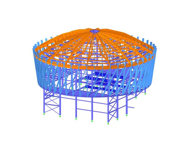
Both RFEM and RSTAB are ideally suited for the structural analysis and design of power plants and conveyor structures. Depending on the requirements, you can use the add-ons from various industries, such as concrete structures or steel structures.
Main Programs RFEM and RSTAB
The main programs RFEM and RSTAB are used to define the model with its properties and actions. For this, RFEM provides more extensive options, as the finite element analysis can also be used for modeling and designing planar structural components.
Add-ons for Power Plants and Conveyor Structures
Various add-ons supplement the functionality of the main programs. In the design add-ons Steel Design and Concrete Design, you can perform the ultimate and serviceability limit state design, as well as the stability analysis according to various standards.
The Torsional Warping (7 DOF) add-on allows you to also perform lateral-torsional buckling analysis with up to seven degrees of freedom. The Stress-Strain Analysis add-on provides the option for general stress design checks, where the existing stresses are compared to the limit stresses. For the plastic design checks, we recommend the Nonlinear Material Behavior add-on.
Dynamic Analysis
If you need to perform a seismic or vibration analysis, the corresponding Dynamic Analysis add-ons are the perfect tools for determining natural frequencies and mode shapes, or for the analysis of external excitations.
In case of any questions about the Dlubal solution for power plants and conveyor structures, our sales team will be happy to assist you.
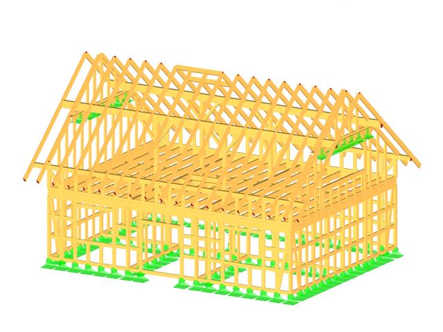
Both RFEM and RSTAB are ideally suited for the structural analysis and design of timber structures.
The main programs RFEM and RSTAB are used to define the model with its properties and actions. In addition to spatial frame and truss structures, such as halls or space trusses, it is possible to model plate, wall, and shell structures with RFEM. Thus, RFEM is the more versatile variant—especially if you work in other areas, such as solid construction.
Available Standards
Add-ons for Timber Structures
Design add-ons supplement the functionality of the main programs. Use the Timber Design add-on to perform the ultimate and serviceability limit state design checks as well as the stability analysis and fire resistance design according to the standards listed above. In combination with the Torsional Warping (7 DOF) add-on, you can also perform lateral-torsional buckling analysis with up to seven degrees of freedom.
The special-solution Multilayer Surfaces add-on for RFEM is ideally suited for laminate surfaces made of cross-laminated timber (CLT).
In case of any questions about the Dlubal timber design solutions, our sales team will be happy to assist you.
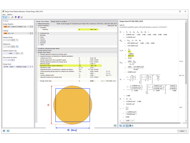
The formula to determine the initial section depth di (CSA) or the equivalent square section dimension aeq (NDS) used for the slenderness ratio calculation is as follows:
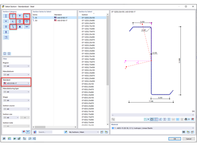
Channels, hats, angles, and Z sections from AISI D100-17 standard can be designed according to AISI S100 in the Steel Design Add-on.
Additionally, all rectangular and round HSS AISC shapes can also be designed per AISI S100. This option is set under the Strength Configuration for Steel Design.
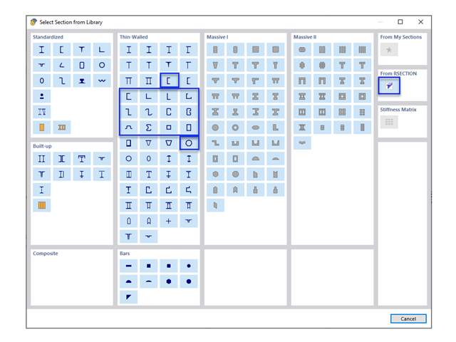
A custom section can be created using one of the “Thin-Walled” sections available in the library. For other sections that do not meet any of the 14 available cold-formed shapes, the sections can be created and imported from the stand-alone program RSECTION.
Parametric (custom) sections with the manufacturing type “Cold formed” can be designed according to AISI S100 or CSA S136.
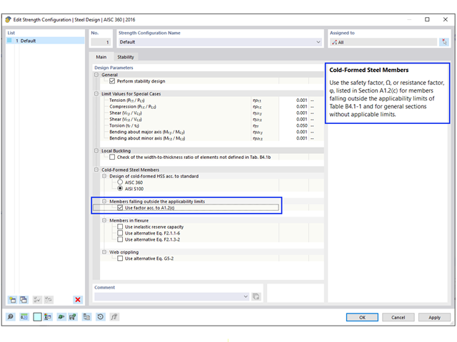
The safety factor Ω and resistance factor Φ used in Chapters E through H are only appropriate for sections that comply with the limitations in Table B4.1‑1. For all other sections that exceed any of the limits, higher safety factors Ω or lower resistance factors Φ are applied according to section A1.2(C). In RFEM, this limitation is checked by default. The user has the option to deactivate this check in the "Strength Configuration".
Shapes that can be checked in RFEM include C, Z, L, I (double back-to-back C), hat, rectangular, and round HSS. In the example shown in Image 02, the 8ZS2.75 x 105 section meets the applicability limits.
For general/complex sections, such as the sigma section used in Example III‑14 of AISI D100‑17 (shown in Image 03), the more conservative factors are automatically applied. As a result, Φc = 0.80 is used in the RFEM design checks. However, the manual calculation shows that the sigma section actually meets the applicability limits and Φc = 0.85 can be used instead.
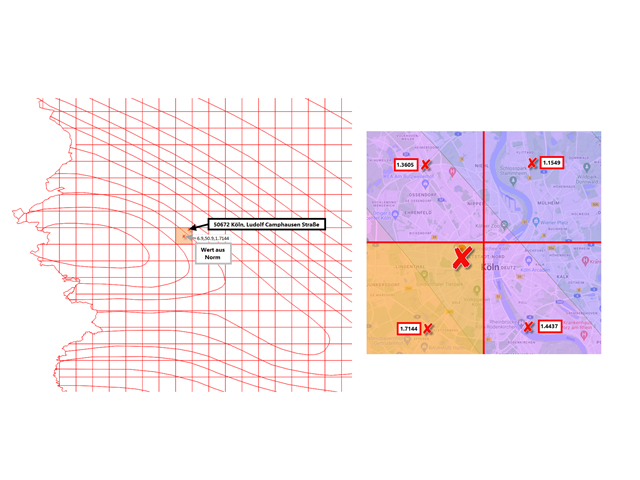
The raw data comes from DIN EN 1998‑1/NA:2021‑07, including the additional digital content. The GPS coordinates and the response acceleration SaP, R in the plateau area of the response spectrum are available in the form of an Excel table. It shows the GPS coordinates for the latitude and longitude in decimal degrees with an accuracy of 0.1°. The geo-zone tool also works with a grid size of 0.1°×0.1°. The values from the additional digital content are defined as a center of each cell. The result of the search query is then taken from the corresponding cell. Intermediate values are not interpolated nor extrapolated. Therefore, it may happen that the color range does not correspond the result from the cell, because the curves do not follow the grid, but lie on a separate layer. This layer has thus no influence on the results and is only used for a better overview.
Example:City: Ludolf Camphausen Street in Cologne
As you can see in the image, the location in the cell is located at 6.9° east and 50.9° north. Thus, the location you are looking for gets a response acceleration of 1.7144 m/s², as it is not interpolated.
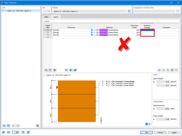
If no angle can be defined in the "Rotation" column, there is an isotropic material model selected for the material, where stiffnesses are identical in all directions and it is not necessary to define an angle.
If you use materials with anisotropic behavior (for example, timber), it is necessary to ensure that the "Orthotropic | Linear Elastic (Surfaces)" material model is selected.
Note: The "Orthotropic | Timber | Linear Elastic (Surfaces)" material model cannot be currently used in combination with the "Layers" thickness type.
As soon as switching to the orthotropic material model, the individual layers can be rotated accordingly.
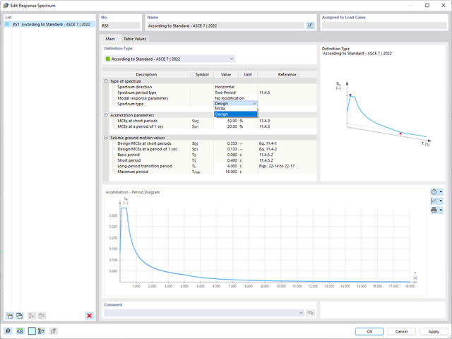
The ASCE 7-22 standard provides several types of design spectra. In this FAQ, we would like to focus on the following two design spectra:
The two-period spectrum is implemented in the program as usual. However, based on the data available from the standard, only the horizontal design spectrum / MCER spectrum as well as the modification related to the force and displacement can be offered.
For the multi-period design spectrum, discrete numerical values are specified. ASCE 7‑22 states that these values can be queried on the USGS Seismic Design Geodatabase page. In the current state of development, you have the option to create a user-defined response spectrum with a g‑factor (depending on the mass conversion constant) to use the data from the ASCE 7 Hazard Tool [1], for example.
Please proceed as follows: