3014 Results
View Results:
Sort by:

Using RSECTION for Export of Revit to RFEM 6
How can I use an RSECTION cross-section when exporting a model from Revit to RFEM 6?

FE Mesh Refinement Factor for Reducing Calculation Time
How can I reduce the calculation time for members with a nonlinear material model in RFEM 6 and RSTAB 9?

Meaning of location_flags of Class members_internal_forces (WebService API)
What is the meaning of the location_flags in the members_internal_forces class of the WebService API?

Different Stresses in Static Analysis and Stress-Strain Analysis
Why are the stresses of the structural analysis different from those calculated with the Stress-Strain Analysis add-on?

Web Queries (API) Geo-Zone Tool: Language Setting
How can I change the language for web queries (API) of Geo-Zone Tool?
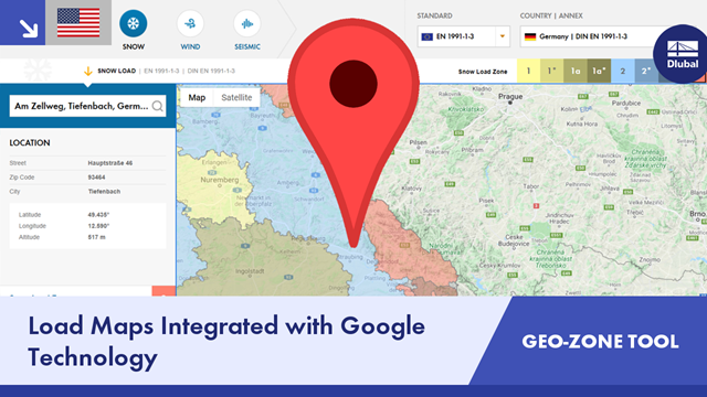
Web Queries (API) Geo-Zone Tool: Loading and Standard Setting
How can I set the loading and standards for web queries (API) of the Geo-Zone Tool?


