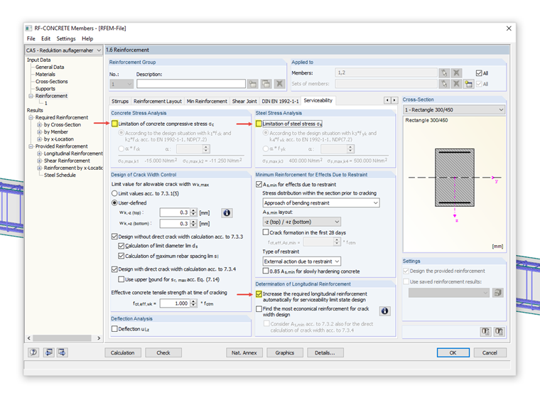
Dimensioning of Longitudinal Reinforcement for Serviceability Limit State Design 1
Tips & Tricks
In the add-on modules RF-CONCRETE Members and CONCRETE and you have the option for "Dimensioning of Longitudinal Reinforcement for Serviceability Limit State". You can select the design criteria for the calculation of the longitudinal reinforcement.
The SLS designs to be performed according to EN 1992-1-1 include, for example:
- Limitation of concrete stress σc according to 7.2 (1)
- Limitation of steel stress σs according to 7.2 (4)
- Minimum reinforcement min As according to 7.3.2 (2)
- Limit diameter lim ds according to Table 7.2
- Maximum rebar spacing lim sl according to Table 7.3
- Limitation of crack width wk according to 7.3.1 (5) and 7.3.4
- Limitation of deflection u according to 7.4
To fulfill the above -mentioned designs for stress limitation, minimum reinforcement, and crack width, you can select the increase of the required longitudinal reinforcement from the ultimate limit state. However, not all designs must always be fulfilled. So you can, for example, do without the design of concrete and steel stresses, if:
- The internal forces have been determined according to the elasticity theory and not more than 15% have been shifted in the ULS design.
- The rules according to Chapter 9 in Eurocode 2 have been observed.
By deactivating individual designs (for example the stress designs) in the "Serviceability limit state" tab, they are not taken into account in the reinforcement design to fulfill the serviceability limit state designs.
Part 2 describes the "Find the most economical reinforcement for crack width design" function.
Author

Dipl.-Ing. (FH) Alexander Meierhofer
Head of Product Engineering Concrete & Customer Support
Keywords
Serviceability stress limitation Reinforcement
Reference
Links
Write Comment...
Write Comment...
Contact us
Do you have questions or need advice?
Contact our free e-mail, chat, or forum support or find various suggested solutions and useful tips on our FAQ page.
New
RF-CONCRETE Members for RFEM or CONCRETE for RSTAB propose an automatically created reinforcement to the user, if the ‘Design the provided reinforcement’ option is selected in Window 1.6 ‘Reinforcement’.
Material Model Orthotropic Masonry 2D
The material model Orthotropic Masonry 2D is an elastoplastic model that additionally allows softening of the material, which can be different in the local x- and y-direction of a surface. The material model is suitable for (unreinforced) masonry walls with in-plane loads.
- When calculating deformations in RF‑CONCRETE Members, I get jumps in the deformation diagram. Why?
- Why can I no longer display the intermediate results in RF‑CONCRETE Members?
- Can I use RF‑CONCRETE Surfaces to determine the steel mass for the inserted reinforcement?
- In connection with the analytical SLS calculation, I get implausibly large values for the crack width and deformation in the RF‑CONCRETE add-on modules. What is the cause and how can I fix the problem?
- When opening an RFEM file, the entries in RF‑CONCRETE Surfaces are lost. Is it possible?
- Is it possible to take a user-defined national annex as a basis for concrete design?
- Is it possible to adjust the initial values of the temperature courses entered for the fire resistance design? For example, I would like to adjust the initial value of the moisture content.
- Regarding a nonlinear analysis of reinforced concrete, is there any feature in the program that increases the load until failure? Or is there any way how to describe the load increment until failure?
- Can I define a beam with a specific reinforcement in RFEM and then obtain design of this reinforcement with the utilization?
- Where can I set partial safety factors for design in RF-CONCRETE Members?
Associated Products