Factor of safety against overturning The structural component is at risk of overturning.
Factor of safety against overturning = 1: The stability moment and the overturning moment are equal. The model is unstable and it cannot be ruled out that it is overturning.
Factor of safety against overturning 1: The model is not at risk of overturning.
Example
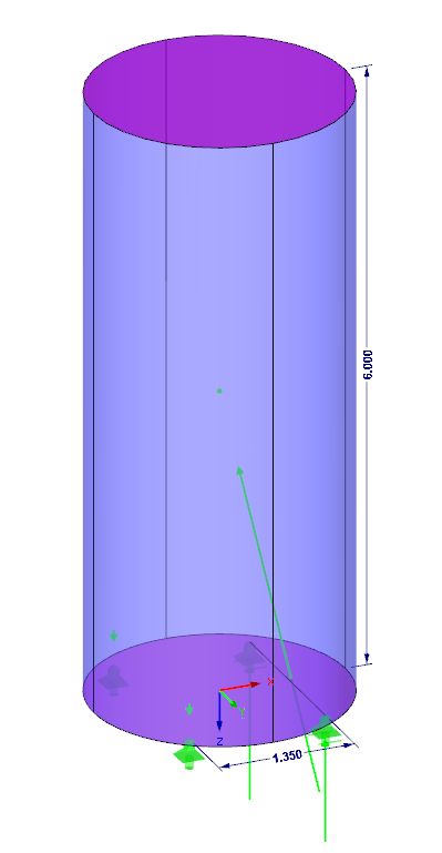
As an example, there is a circular cylinder with a diameter of 2.5 m and a height of 6 m. It is located in the wind load zone 2 with the terrain category 3.
Fundamental value of the basic velocity:
vb0 = 25.0 m/s
Directional factor:
cdir = 1
Season coefficient:
cseason = 1
Air density at the atmospheric pressure of 1,013 hPa and T = 10° C:
ρ = 1.25 kg/m³
Kinematic viscosity of the air:
ν = 15 ∙ 10 -6 m 2/s
Basic velocity:
vb = cdir ∙ cseason ∙ vb0 = 25.0 m/s
Basic velocity pressure:
qb = 1/2 ∙ ρ ∙ vb2 = 0.391 kN/m²
Peak velocity pressure:
qp = 1.5 ∙ qb = 0.586 kN/m²
Peak velocity:
Equivalent surface roughness:
k = 0.2 mm (galvanized steel)
Ratio of equivalent surface roughness and width:
k / b = 8 ∙ 10-5
Reynolds number:
Force coefficient of cylinders without free-end flow:
Effective slenderness:
λ = l / b = 2.4
End-effect factor:
ψλ = 0.65
Structure coefficient:
cscd = 1
Reference area:
Aref = l ∙ b = 15 m²
Force coefficient:
cf = cf0 ∙ ψλ = 0.498
Wind force:
Fw = cscd ∙ cf ∙ qp ∙ Aref = 4.377 kN
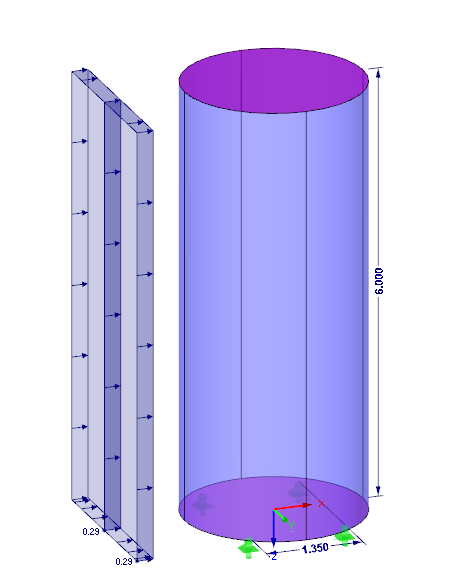
Surface load due to the wind:
Fw = Fw / Aref = 0.29 kN/m²
Stability Factor Due to Overturning
Height of circular cylinder:
h = 6 m
Distance between supports:
a = 1.35 m
Self-weight:
FG = 18.495 kN
Overturning moment:
MK = Fw ∙ h / 2 = 13.13 kNm
Stability moment:
MS = FG ∙ a / 2 = 12.48 kNm
Factor of safety against overturning:
η = MS / MK = 0.95
If you use RFEM for the calculation, you can recognize from the position of the resultants that they are within its extension behind the overturning edge of the circular cylinder. Thus, the model would be unstable if the supports were not additionally secured against pulling out.