


Structural System
Image 01 shows the symmetric structure of a point-supported flat slab with 16 panels in total. The model is generated in the general data of RFEM as 2D structure with the degrees of freedom (uZ/φX/φY).
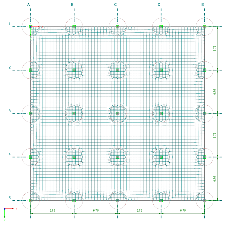
The following structure properties are given:
- Span of a panel: 6.75 m
- Number of panels: 4 x 4
- Slab thickness: 24 cm
- Material: Concrete C35/45
- Column dimensions: 45/45 cm
The question arises as to whether the slab should be modeled as one large surface, or by using 16 single surfaces. Each of these options offers certain advantages: An entire surface can be modeled more quickly. In addition, the distribution of the internal forces mx and my is clear and unproblematic with regard to the smoothing due to the uniform local surface axes. 16 surfaces, however, allow the simple assigning of surface loads by fields and the reliable determination of the surface boundary lines in the FE mesh. With regard to the load combinations (see below), modeling as one large surface is chosen here. In this case, the loads have to be applied as free rectangular loads.
The columns are modeled as elastic nodal supports. The function shown in Image 02 is used to determine the spring stiffnesses.
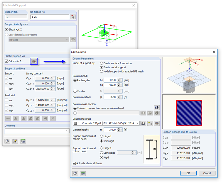
The determination of translational and rotational springs is carried out by taking the boundary conditions of the columns. A column height of 3.00 m and a restraint at the column base are applied here.
With this semi-rigid support, singularity effects as described in Knowledge Base Article 000681 can be avoided. The column areas are thus not part of the internal forces display so that the design moments are generated as realistic as possible. This approach is also described in Knowledge Base Article 001503.
- KB | Dlubal RFEM 5 – Elastic Nodal Support 1
- Singularities in Design of Reinforced Concrete Surfaces
Loading
In Load Case 1, the self-weight of the plate is considered automatically. A fixed load of gk = 1.25 kN/m² is additionally applied to the whole surface.
The imposed load including boundary wall allowance of qk,1 = 3.25 kN/m² (Category A "Residential Areas", according to Eurocode 1 [1]) is used for the following combinations in separate load cases:
- Load on the entire surface
- Load on "odd" panels (checkered distribution, see Image 03)
- Load on "even" panels (checkered distribution)
- Load on panels between Axes 1 and 3 as well as Axes 4 and 5
- Load on panels between Axes 1 and 2 as well as Axes 3 and 5
- Load on panels between Axes A and C as well as Axes D and E
- Load on panels between Axes A and B as well as Axes C and E
These seven options aim at determining the extreme values of supporting and panel moments. It is not difficult to generate the load combinations manually for this symmetrical and clearly arranged model. The loading of the inner panels only is not relevant for the extreme values of all columns. The columns in Axis 3 and C are reinforced in the same way as the other columns.
For comparison: If the loads were defined by panel in 16 load cases and managed in load combinations, it would result in more than 65,000 combination options.
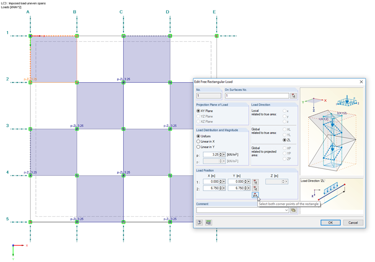
The imposed loads are applied each as free surface loads. The column nodes serve as edge nodes of the load position, which can each be selected graphically. If the free load is defined for Surface 1 as shown in Image 03 (instead of for all surfaces), the coloring of the load is also visible in the Z-view.
Another option is to define the imposed load by field in load cases and to superimpose it with the permanent load in a result combination. This procedure is the reliable and generally recommended option if it is not possible to decide which combination provides the governing internal forces. RFEM forms the enveloping here from the actions of the permanent load and the imposed loads. This option is, however, less transparent with regard to the evaluation of the plate internal forces that are present for the different combinations.
Load Combination
The integrated combinatorics is used for the superposition of the load combinations. Load Case 1 represents the permanent action. Load Cases 2 through 8 act as variable free actions that have to be viewed alternatively.
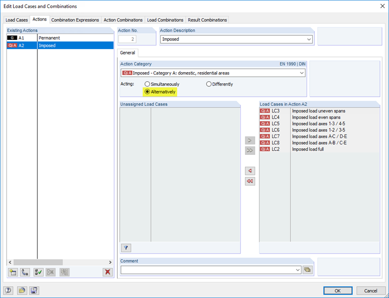
The combination of the actions for the serviceability limit state is carried out for the permanent and transient design situation according to Eurocode 0 [2], (6.10). Since no axial forces are present in this 2D structure, the determination of internal forces is carried out geometrically linear according to the second-order analysis.
According to these settings, RFEM generates eight load combinations with consideration of the corresponding partial safety factors. These load combinations are taken over in a result combination as alternatively acting which provides the extreme values of the individual combinations.
The calculation thus covers the enveloping internal forces sufficiently precise and remains clear at the same time. If the load cases were defined by panel, the capacities of the program would be exceeded significantly.
Mesh of Finite Elements
A length of 45 cm for the FE elements is planned because the column dimensions amount to 45/45 cm, and 45 cm is also a multiple of the panel length of 6.75 m. RFEM uses triangular and quadrangle elements for the automatic mesh generation.
The singular supports are each connected at an FE element, with the dimensions of the column cross-section being 45/45 cm. No results are displayed for this FE element. However, this element influences the surrounding FE mesh in the column area. To ensure a sufficient exact number of result values in the area of the supporting moments, circular FE mesh refinements are assigned.
The settings for the FE mesh are as follows:
- FE length in general: 45 cm
- FE mesh refinement: circular at all support nodes
- Radius for refinement: 1.35 m
- FE length inside: 20 cm
- FE length outside: 45 cm
With these settings, the FE mesh is generated as shown in Image 01.
Internal Forces
RFEM calculates the slab internal forces with the FE method. The column moments are displayed at the column edges; they represent the gate moments. The areas of the column areas themselves are without internal forces.
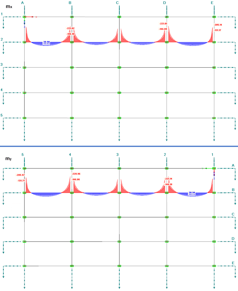
Image 05 shows the extreme values of the support and panel moments in the governing sections: The diagram of the moments mx in Axis 2 is shown above, the diagram of the moments my in Axis B is shown below. As expected, a corresponding distribution is the result due to the symmetry of the structure.
Beding Design in RF-CONCRETE Surfaces
In the RF-CONCRETE Surfaces add-on module, the result combination RC1 is selected for the ultimate limit state design according to EN 1992-1-1 [3] with German National Annex. Concrete C35/45 and reinforcing steel B 500 S (A) are selected as material for the design.
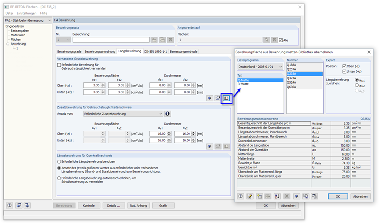
In the "Longitudinal Reinforcement" tab of Window "1.4 Reinforcement", mesh number Q335A is selected as the basic reinforcement from the library for the top and bottom layers. Rebars with a diameter of 16 mm are defined for the additional reinforcement.
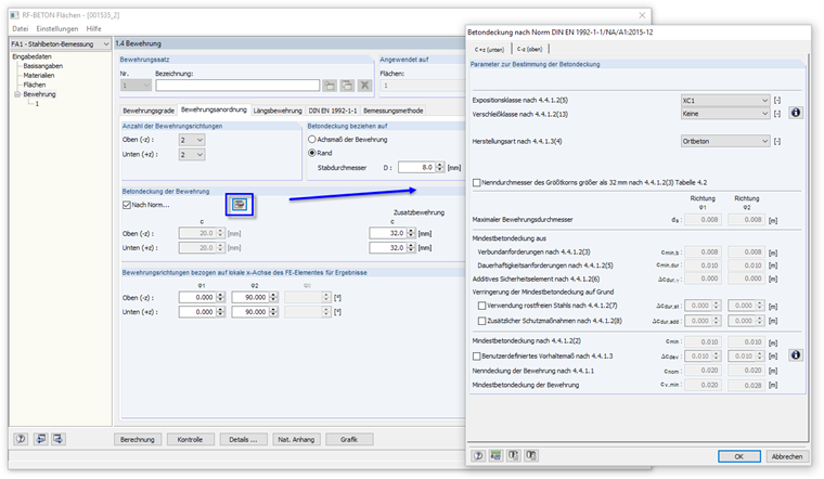
The concrete cover is defined in Table "1.4 Reinforcement", the tab titled "Longitudinal Reinforcement", according to the standard for exposure class XC1. The concrete cover is related to the edge of the rebars. The first reinforcement direction is oriented parallel to the global X-axis (angle φ = 0°), the second reinforcement direction to the Y-axis (angle φ = 90°).
With these settings, it results in the following effective depths:
- Reinforcement direction: 21.6 cm
- Reinforcement direction: 20.8 cm
The design of the so-called "Mixed Method" (preset in the "Details" dialog box) is reliable enough for the design of only one result combination to determine all extreme values of the slab moments. Another option is to analyze the eight load combinations directly in the design case.
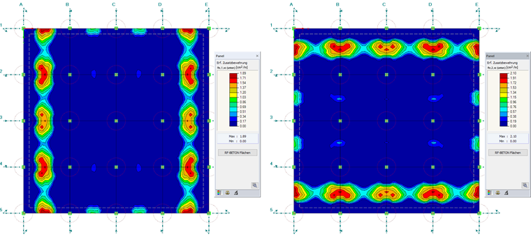
The design results in the required reinforcement areas shown in Image 08 for the distribution of the support moments in the Axis 2 and B.
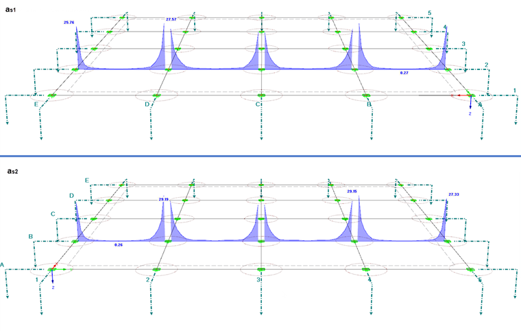
The panel moments are largely covered by the basic reinforcement. An additional reinforcement of a maximum of 2.10 cm²/m is only necessary at the edge panels.
Result Evaluation
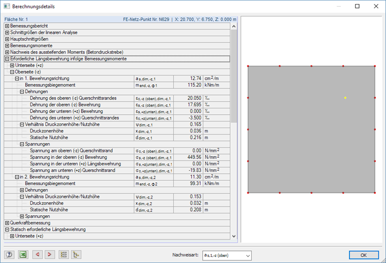
The design details, which can be opened in each result table, allow a pointwise evaluation of the design checks. They contain, amongst others, information about the design moments, stresses and strains of the concrete and reinforcing steels as well as the reinforcement ratios. The relevant design type has to be set below in the dialog box.
The results of the reinforced concrete design can be evaluated graphically in the RFEM work window. It is possible to display separately the required reinforcement, the additional reinforcement, and the basic reinforcement for the individual reinforcement layouts and directions.
The panel manages the color assignment of the reinforcement areas. Colors and values can be customized here. For RF-CONCRETE Surfaces, it is possible to display reinforcement surfaces additionally which result from certain rebar diameters and rebar spacings. The color and value scale has to be modified here by using the panel button.
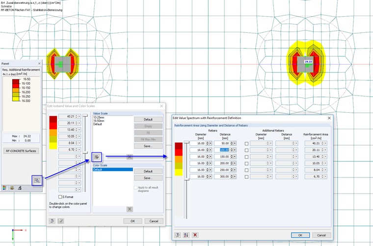
The user-defined color and value scales can be saved and therefore be used for all models.
As shown in Image 11, the additional reinforcement at the top above the columns can be covered by rebars with Ø 16, which are placed at a distance of 10 cm at a width of 1.20 m (to compare: the radius of the refinement area shown in the image amounts to 1.35 m). Taking into account the anchorage lengths, rebars with l = 2.00 m can be defined for example. The corresponding design according to [3], Section 8.4, is performed separately. The steel stresses can be taken from the design details as shown in Image 10.
Outlook
The bending design of a slab for the ultimate limit state was presented in this article. The determination of internal forces and the design is performed according to the linear analysis. A nonlinear design for the serviceability limit state can be also performed in RF-CONCRETE Surfaces. It is, however, necessary here to change the model type to 3D in the general data, since the nonlinear calculation considers also the surface axial forces.
Moreover, the punching shear designs in the area of the nodal supports have to be performed. In Knowledge Base Article 001389, it is described how the punching shear of a slab can be determined with the RF-PUNCH Pro add-on module.