


General
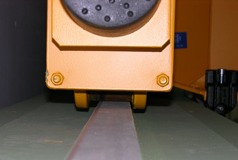
According to the current state of technology, there are two systems to implement the lateral guiding of crane wheels. Flanges are used in light to medium crane operation. Here, the lateral guiding occurs by grinding the flange on the rail. The advantage of this method is the simple setup. Apart from the crane wheel with flange and the craneway rail, no additional technical equipment is necessary for the lateral guiding of the crane. The disadvantage of this method is the wear that occurs on the wheel and rail. Figure 01 shows an impeller with a wheel flange on a KS rail.
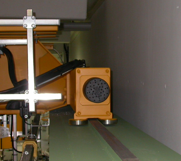
The second solution is the use of lateral guide rollers. In this case, the actual crane wheel does not need to have a flange; it can move freely from side to side on the craneway rail, apart from friction. If wheel flanges are still present, they serve only as a derailment guard. The inevitable skewing of the crane is hampered by lateral rollers, which are either in the position of the crane wheels or arranged in front of or behind the axles of the crane. The advantage of this solution is the significantly reduced track guiding forces, since the lateral guide rollers are always pressed to the crane rail by a spring. Likewise, the wear of the lateral guide rollers and the crane wheel is significantly less. However, this type of lateral guiding requires a certain assembly space next to the crane rail and leads to higher acquisition costs. Figure 02 shows the guiding via lateral guide rollers on a KS rail.
Determining the Forces from Skewing
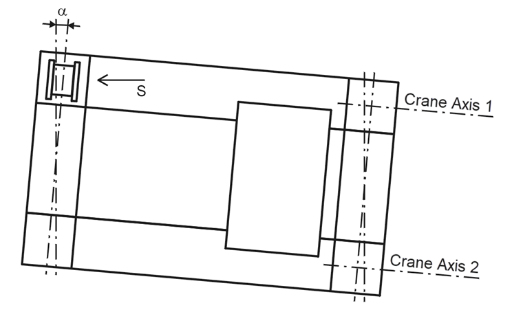
Dimensional deviations, wear, and play in the lateral guiding lead to skewing of the crane. Here, a slip angle α arises between the crane axles and the craneway axle (see Figure 03).
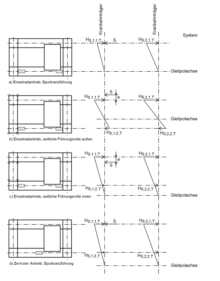
The magnitude of the horizontal reaction forces from skewing is influenced by various boundary conditions. In addition to the type of lateral guiding, the position of the guide and the chassis system of the crane wheels are crucial. The dimensions of the crane, the position of the overall centroid, and the sum of all wheel loads likewise influence the magnitude of the skewing forces. Figure 04 shows four design variants and the resulting horizontal reaction forces, including alignment.
The crane manufacturers always provide the lateral guiding forces in the data sheets of the cranes. If the crane manufacturer is not yet known at the time the crane girder is being dimensioned, the lateral guiding forces for bridge cranes can be determined in a simplified manner according to DIN EN 1991-3, Chapter 2.7.4 [1].
Example and Input in CRANEWAY
For this article, the company ABUS Kransysteme was kind enough to provide the data sheet of a double girder crane (ZLK) with a load capacity of 10 t. The crane is unilaterally guided by lateral guide rollers. Figure 05 shows the load actions according to DIN EN 1991-3 in tabular form. Below the table is a schematic representation of the crane from above with indication of the load arrows and load designations.
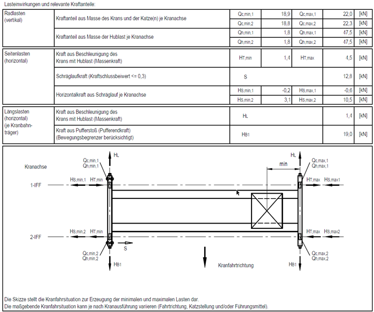
For an economic dimensioning, the application of the lateral guiding forces (as well as the other horizontal mass forces) in the right direction and on the right girder is of particular importance. In CRANEWAY, the loads can be defined for a girder with maximum wheel loads and for a girder with minimum wheel loads. While doing so, the movement direction of the crane and the designation of the crane wheels must be observed, as well as the positive direction of the respective load based on the alignment of the load arrows in the graphic. Figure 06 shows the skew force S and the associated horizontal forces HS per crane axis.
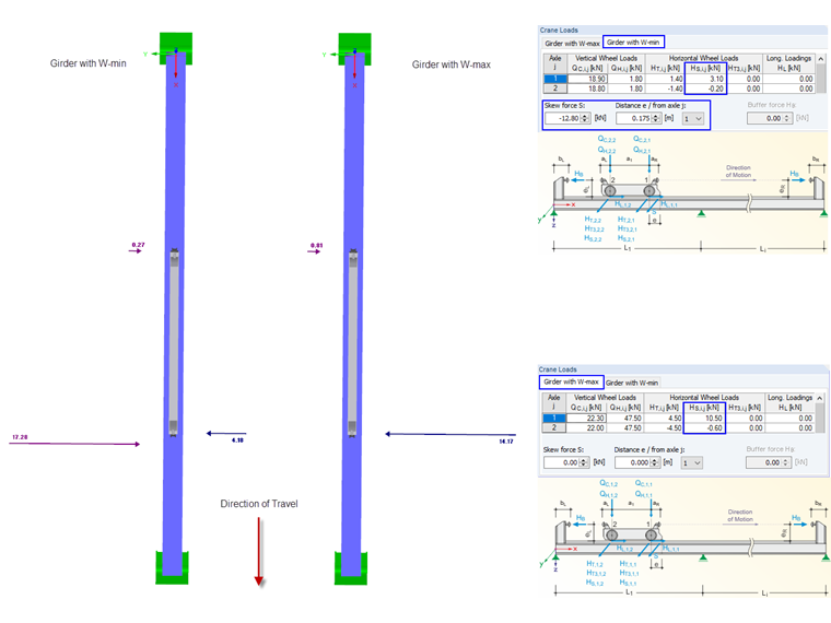
The displayed values are determined as follows.
Girder with W-min:
Sd = γQ ⋅ S = 1.35 ⋅ 12.80 = 17.28 kN
HS,min,2,d = γQ ⋅ HS,min,2 = 1.35 ⋅ 3.10 = 4.18 kN
HS,min,1,d = γQ ⋅ HS,min,1 = 1.35 ⋅ -0.20 = -0.27 kN
Girder with W-max:
HS,max,2,d = γQ ⋅ HS,max,2 = 1.35 ⋅ 10.50 = 14.17 kN
HS,max,1,d = γQ ⋅ HS,max,1 = 1.35 ⋅ -0.60 = -0.81 kN
Summary
Forces from skewing are unavoidable for craneways. However, with the right choice of lateral guiding, economic solutions can be found for the respective case of application. This requires the correct application of the lateral guiding forces, however. This article helps to make working with CRANEWAY easier for the user.