


For the general example provided in this article, a 3D timber structure will be used which includes a curved timber roof extending to the foundation. The clear span of a single timber arch is 64 ft, and the height from the base to the crown of the arch is 16 ft.
.png?mw=760&hash=98b2f1246383943431fc6a42aea24106d857b661)
Snow Loads from ASCE 7-16
Figure 7.4-2 [1] within the standard identifies how to clearly load a curved roof for both balanced and unbalanced snow loads. The downward snow load application varies along the arch length dependent upon the roof's slope at a specific location. Therefore, it is necessary to determine the slope in degrees along the entire arch length.
Determining Roof Slope
Converting the elevation view of the arch roof into a simple line element and projecting onto an x and y coordinate system, the x coordinate points are determined at a 1-foot increment along the base of the structure. Knowing the arch from the structure example is only a portion of a larger circle, the equation for a circle can be utilized to determine additional info about the arch length.
|
x |
Coordinate of an arch along the x axis |
|
y |
Coordinate of an arch along the y axis |
|
h |
x coordinate of the circle center |
|
k |
y coordinate of the circle center |
|
r |
Radius or the circle |
Rearranging the above equation, since all values are given other than the y coordinate of the arch, the equation becomes:
To find the slope of a point anywhere along the arch, implicit differentiation must be applied to the equation of the circle with respect to x.
Solving the implicit differentiation, the slope rise/run which is denoted by dx/dy is found to be the following.
To determine the slope in degrees, the inverse tangent function is applied.
Additionally, the equation above for "y" can be substituted in the slope equation, since this value may not be readily known when comparing to the known x coordinate point. It is now possible to determine the slope in degrees along every x location for the structure arch.
Snow Load Magnitude
According to Fig. 7.4-2, there are three different cases depending on the curved roof geometry at the roof edge or eave.
- Arc slope at the eaves < 30°
- Arc slope at the eaves 30° to 70°
- Arc slope at the eaves > 70°
For each case, both a balanced and an unbalanced loading are given along the arch length. Snow load acting on a sloping surface is applied in the horizontal projection of the surface. Fig. 7.4-2 summarizes these load values by multiplying the flat roof snow load pf by the Roof Slope Factor Cs. Cs accounts for the varying slope along the arch length and is dependent on several factors indicated in Figure 7.4-1 [1], including the Thermal Factor Ct found in Table 7.3-2 [1], the surface type (that is, unobstructed slippery surfaces versus all other surface types), and the roof slope in degrees, which was determined in the Slope equation above.
The Exposure Factor Ce is needed for the snow load magnitude at locations where the arch slope varies between 30° and 70° indicated in Fig. 7.4-2 for the unbalanced load scenarios only. This value can be determined from Table 7.3-1 [1] depending on the terrain category and roof exposure condition.
The flat roof snow load is determined from Eqn. 7.3-1 [1] shown below.
pf = 0.7 ⋅ Ce ⋅ Ct ⋅ Is ⋅ pg
Where Ce and Ct are discussed above and found in Tables 7.3-1 and 7.3-2, respectively. The Importance Factor Is is found in Table 1.5-2 [1], which is further dependent on the Risk Category from Table 1.5-1 [1]. The ground snow load pg can be found in Fig. 7.2-1 [1] and Table 7.2-1 [1].
Dlubal Software has integrated the ground snow load maps found directly in ASCE 7-16 with Google Maps Technology to create the Geo Zone Tool available on the Dlubal website. This tool allows the user to set the address of the project location or to click directly on the map. In return, the Geo-Zone Tool will automatically display the snow, wind, and seismic data based on ASCE 7-16 for the specified location. This provides a more efficient and simpler alternative in comparison to manually locating this info from the standard to determine ground snow loads for various locations within the United States.
Snow Load Location
For all three snow load cases for curved roofs, the magnitude varies along the arch length depending on the roof slope shown in the loading diagrams in Fig. 7.4-2. The major locations needed for any of the three cases are 70°, 30°, and the crown. With the Slope equation above, these specific points can easily be determined along the arch length. The magnitudes vary linearly between these specific location points, so it is unnecessary to evaluate the snow load magnitude at each slope point.
For the balanced load scenarios, the magnitude of the arch to the left and right of the crown is set as Cs ⋅ pf, where Cs = 1.0. Therefore, the user is required to determine at which corresponding roof slope location the Cs factor is equal to 1.0 based on Figure 7.4-1. Once this roof slope is determined, the point along the arch length can be found based on the information from the Slope equation.
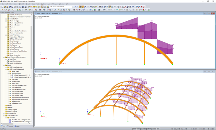
For unbalanced load scenarios, the windward side is considered free from snow. Snow load will only be applied to the arch along the leeward side, as indicated in the loading diagrams. If another roof abuts to the current roof, the diagrams also indicate how to consider these special cases in the unbalanced load cases for both load magnitude and location.
Application in RFEM
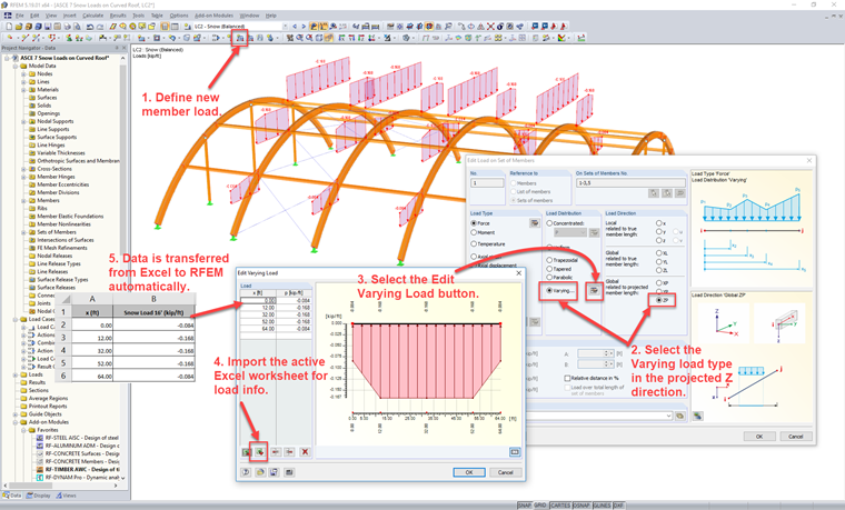
Complex loading scenarios are easily handled in RFEM with the available tools. Likely, the easiest scenario for calculating the roof slope at all locations along the arch length indicated by the initial equations described above is to utilize a spreadsheet program such as Microsoft Excel.
With the calculated roof slope and the steps above taken to determine the snow load magnitude from ASCE 7-16, the loads can be simplified in Excel to a few extreme locations, where applicable, such as the roof eaves, 70°, 30°, and the crown. This information can be set up in table format defined in a single spreadsheet with the x location defined along the projected x axis of the arch and the corresponding snow load magnitude.
In RFEM, select the "new member load" tool to apply to either members or sets of members. The "Varying" load distribution will be used in the projected Z direction ZP. Additionally, select the "Edit Varying Load" button to activate the table within the program. With a single click, all info currently defined in the active Excel worksheet can be imported directly into the RFEM table.
The same scenario can be followed for a separate load case within RFEM to apply the unbalanced snow loading.
The ability to import varying loads directly from Excel can be extremely helpful for multiple member load application and where the load magnitude varies significantly along the member length.