


This article describes two ways to determine the accidental torsional actions in RFEM and RSTAB.
Automatic Determination in RF-/DYNAM Pro – Equivalent Loads Add-on Module
It is possible to determine the accidental torsion automatically in the RF-/DYNAM Pro – Equivalent Loads add-on module. This option can be activated under "Dynamic Load Cases" in the "Equivalent Force Analysis" tab. When using this option, only the value of the eccentricity is required in the add-on module. In EN 1998-1, this value is 5% of the building's length or width in the direction acting perpendicular to it. In RFEM and RSTAB, this value must be entered in the respective direction:
- ex = 0.05 ⋅ Lx
- ey = 0.05 ⋅ Ly
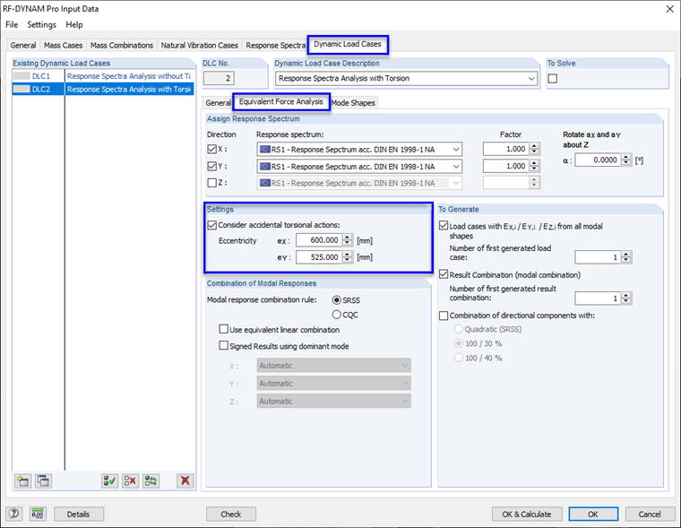
Based on this eccentricity, which is multiplied by the equivalent load, the add-on module determines a torsional moment that is applied to each FE node or internal node (for each individual load case). The formula is:
M = |Fx ⋅ ey| + |Fy ⋅ ex|
Due to the application of a torsional moment locally in each FE node, high torsional stress may occur in the individual structural components. To prevent this, the torsional action must be applied manually. It is described in the following text.
Manual Determination of Accidental Torsional Actions
A more economical way to consider accidental torsional actions is to apply a global torsional moment. This results from the total seismic loads per story and must be distributed to the individual shear walls of a building. This procedure usually leads to more economical results and complies with the standards.
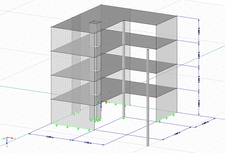
As an example, this method is described for a building that is regular in its layout and has an L-shaped ground plan. A response spectrum analysis is performed in the RF-/DYNAM Pro – Equivalent Loads add-on module. Two result combinations are the result, one for the X-direction and the other for the Y-direction of the building. The evaluation is done by means of a result beam, evaluating the shear forces (Vy and Vz) per story (Vz corresponds to the seismic force in the X-direction → Fx, and Vy corresponds to the seismic force in the Y-direction → Fy). This seismic load per story is then multiplied by the eccentricity (5% of the vertical building length) and both directions are added, resulting in a torsional moment per story. The results are listed below.
Results of Result Combination 1 (earthquake in the X-direction):
| Fx | Fy | ex | ey | M | |
|---|---|---|---|---|---|
| 4th floor | 138.0 kN | 70.4 kN | 0.60 m | 0.525 m | 119.8 kNm |
| 3rd floor | 91.0 kN | 56.0 kN | 0.60 m | 0.525 m | 84.0 kNm |
| 2nd floor | 56.9 kN | 30.5 kN | 0.60 m | 0.525 m | 50.2 kNm |
| 1st floor | 21.6 kN | 4.5 kN | 0.60 m | 0.525 m | 15.3 kNm |
Results of Result Combination 2 (earthquake in the Y-direction):
| Fx | Fy | ex | ey | M | |
|---|---|---|---|---|---|
| 4th floor | 71.5 kN | 113.4 kN | 0.60 m | 0.525 m | 102.4 kNm |
| 3rd floor | 55.5 kN | 66.8 kN | 0.60 m | 0.525 m | 68.4 kNm |
| 2nd floor | 29.9 kN | 46.1 kN | 0.60 m | 0.525 m | 42.1 kNm |
| 1st floor | 4.6 kN | 17.6 kN | 0.60 m | 0.525 m | 12.0 kNm |
For distributing the torsional moment correctly on the individual shear walls, the SHAPE-THIN cross-section program can be used, as the calculation of non-connected cross-sections according to the theory of stiffening systems is possible. Accordingly, the ground plan (all shear walls; columns are irrelevant in the stiffening) is modeled and loaded by a unit torsional moment of 100 kNm. The result is a resulting shear force per wall.
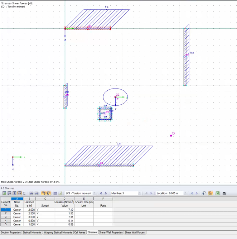
Since these shear forces were calculated for a unit moment of 100 kNm, they have to be determined for the actually occurring moments per story. The values can be multiplied by the moment shown in the table and divided by 100. These forces per wall have to be applied in the building model as line loads (divided by the wall length).
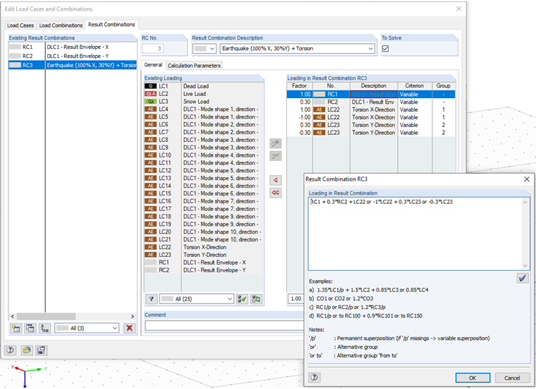
Thus, two new load cases are the result: Torsion in the X-direction and torsion in the Y-direction. Subsequently, these load cases can be superimposed in a new result combination with the OR condition and combined with the seismic loads. Then, we get the final results: the resulting seismic loads, including correct application of the accidental torsion.
A detailed description of this method, as well as tips and tricks for entering data, can be found in the linked webinar (only available in German).
