


General
In architecture, it is common to work with solid models. The position of beams and columns relative to each other is taken into account by the expansion of the cross-section. In structural analysis, simplified line models are used where the center lines meet in a node. In RFEM and RSTAB, you can also display this simplified model as rendered. The intersections of the individual components often disturb the appearance and may lead to questions from the client. Member eccentricities are often used to approximate the representation of the structural model to that of the architectural model. This technical article uses three very simple models to illustrate the influence of member eccentricity on the determination of internal forces.
Model 1 Without Member Eccentricities
Beam and column meet in Node 2. No member eccentricities are used.
Image 01 shows the rendered model on the left. The beam only extends to the center line of the column. The column also extends to the center line of the beam.
The beam is loaded with a line load of 50 kN/m and an axial force of 50 kN. The self-weight of the members is neglected for simplification.
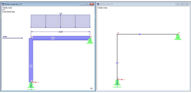
Since the column support is free in the X-direction, the bending moment and the shear force of the beam are obtained in this model as for a single-span beam.
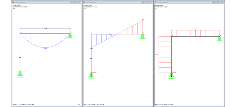
Image 02 shows the internal forces My, Vz, and N.
Model 2 with Member Eccentricity, Axial Offset
Member 10 is guided to the outer edge of the column by an axial offset of 150 mm. This extension of the beam also increases the loading.
Image 03 shows the rendered model on the left.
The beam is loaded with a line load of 50 kN/m and an axial force of 50 kN. If the self-weight were taken into account, it would also be increased.
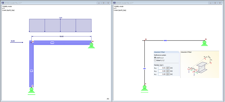
The axial offset leads to an extension of the member. The free member end is rigidly connected with Node 14.
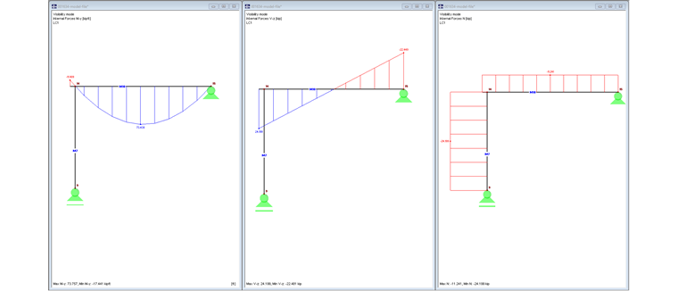
The acting shear force of 107.64 kN at the edge causes a negative bending moment:
My = 107.64 kN ⋅ -0.15 m = -16.15 kNm
Increasing the vertical load amounts to 50 kN/m ⋅ 0.15 m = 7.50 kN.
Image 04 shows the internal forces My, Vz, and N.
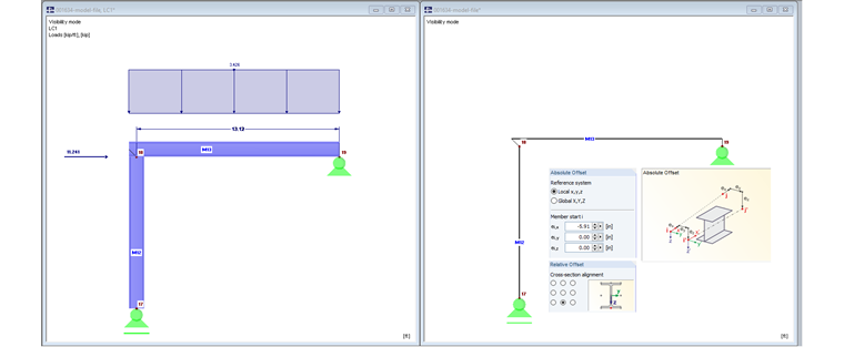
Model 3 with Member Eccentricity, Axial Offset, and Transverse Offset
Member 13 is guided to the outer edge of the column by an axial offset of 150 mm. Furthermore, the beam is positioned with its lower edge on the upper edge of the column by a relative transverse offset.
Image 05 shows the rendered model on the left.
The beam is loaded with a line load of 50 kN/m and an axial force of 50 kN. If the self-weight were taken into account, it would also be increased.
The axial offset leads to an extension of the member. The free member end is rigidly connected with Node 18.
The acting shear force of 107.64 kN at the edge causes a negative bending moment:
My = 107.64 kN ⋅ -0.15m = -16.15 kNm
Increasing the vertical load amounts to 50 kN/m ⋅ 0.15 m = 7.5 kN.
The vertical transverse offset of 150 mm leads to an additional constant moment due to the acting axial force of 50 kN:
My = 50 kN ⋅ -0.15m = -7.50 kNm
The negative corner moment due to the use of member eccentricity is increased by:
My = -16.15 kNm + (-7.50 kNm) = -23.65 kNm
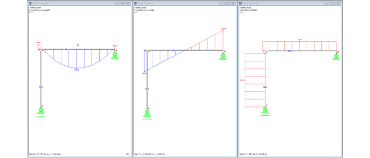
Image 06 shows the internal forces My, Vz, and N.
Conclusion
Properly used member eccentricities can lead to a more accurate structural system. These simple examples illustrate that, however, eccentricities also lead to changes in the internal forces and, in the case of complex systems, it can sometimes be difficult to trace back to the application of the member eccentricities.