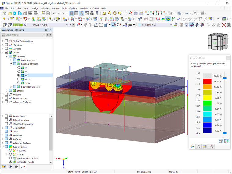
Hence, we assume that the Geotechnical Analysis add-on has been activated, the data obtained from field tests have been inserted, and the soil massifs of interest have been determined as explained in the above-mentioned article. We also assume that the reinforced concrete building has been modeled (loads included) as shown in Image 1.
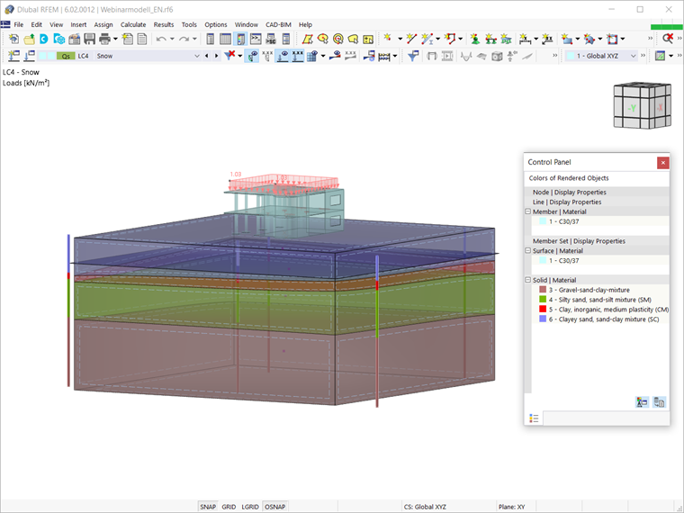
What you have to do now is to define the load and result combinations to be calculated. To do so, you can open the Load Cases & Combinations window. The loads that have been applied to the superstructure are shown in Image 2 and they include the self-weight, dead and live loads, and snow. When the Geotechnical Analysis add-on is activated, you may notice that only the self-weight of the building is considered in the associated load case.
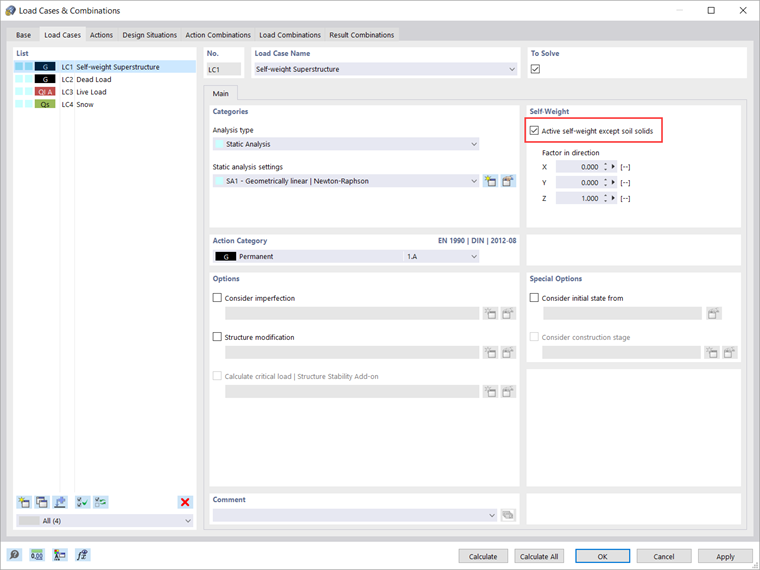
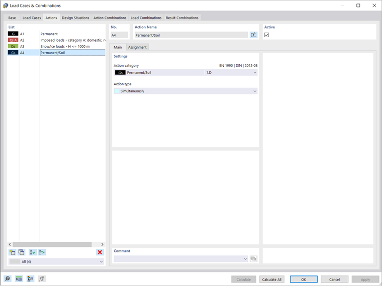
Thus, you have to create a separate load case in which the self-weight of the solid will be activated, as shown in Image 3. That being the case, the action category in this load case should be assigned as Permanent/Soil. Although all loads are related to a separate load case, it is important to understand that for the geotechnical analysis, you should consider them in load and result combinations rather than as single load cases.
For instance, the live load will be applied to the model only after the self-weight of the solid, the self-weight of the superstructure, and the dead load are active. To take this into account, you should deactivate all load cases associated with the superstructure by unchecking the "To Solve" icon, leaving only the load case for the self-weight to be solved (Image 3). By doing so, the load cases of the superstructure still exist, but instead of being calculated as single load cases, they are calculated in load and result combinations.
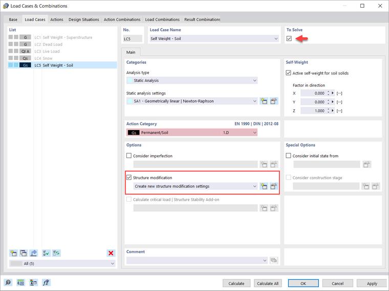
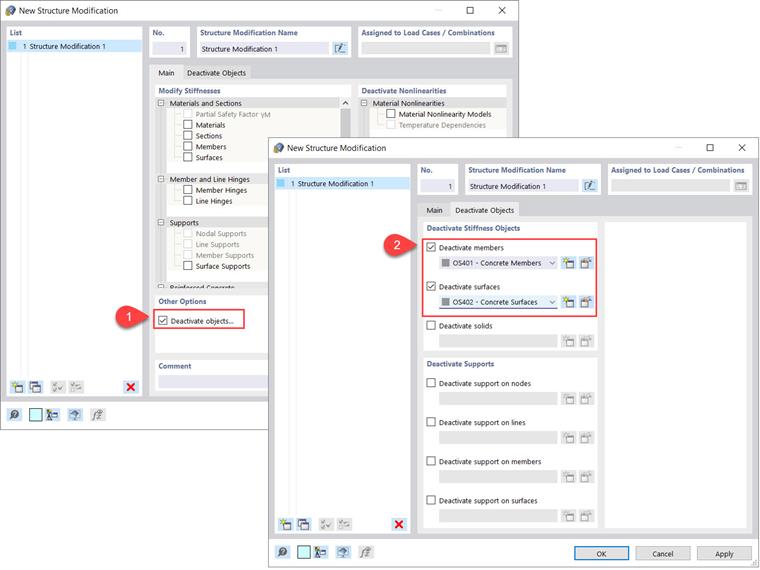
When defining the "Self-weight Soil" load case, you should create new structure modification settings by activating the associated check-box (Image 3). In particular, you have to deactivate concrete members and surfaces as shown in Image 4.
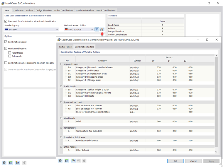
To define the load and result combinations automatically, you have to first activate the associated wizards in the Base Data of the Load Cases & Combinations window, as shown in Image 5. The combination wizard assists you in classifying the load cases in compliance with the standards and superimposing them in action and design combinations.
In other words, the load cases are combined according to the preferred standard specification, which by default is the standard you defined in the model's Base Data. However, you can also select a different standard in the "Standard group" list, and you can check the parameters of the combination wizard in the "'Edit Combination Wizard" dialog box. When employing the Result combinations wizard in addition to the Load combinations wizard, the results of the load cases or combinations are superimposed as well.
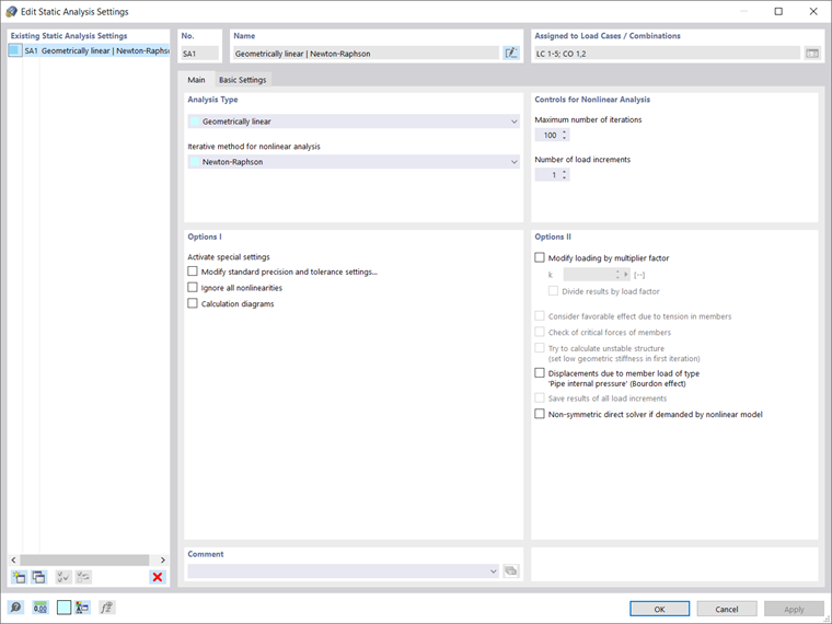
Before going further, you can edit the static analysis settings for the load case for the self-weight of the solid as shown in Image 6. For instance, you can change the maximum number of iterations, or the number of load increments for the nonlinear analysis. In this example, the former is set to 100, whereas the latter is set to 1.
Once the load cases have been defined, you can see all the action categories that are applied to the model in the Actions tab of the Load Cases & Combinations window (Image 7). Next, you control the design situations that have been created. In other words, you can activate or deactivate all the design situations that are available in the list.
Since we are interested in the calculation of settlements, only the quasi-permanent design situation (Image 8) should be considered; therefore, all other design situations except the quasi-permanent situation will be deactivated. The information about combination rules for the situation of interest is available as well.
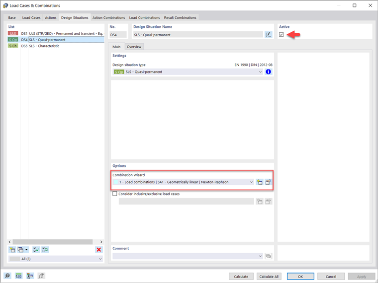
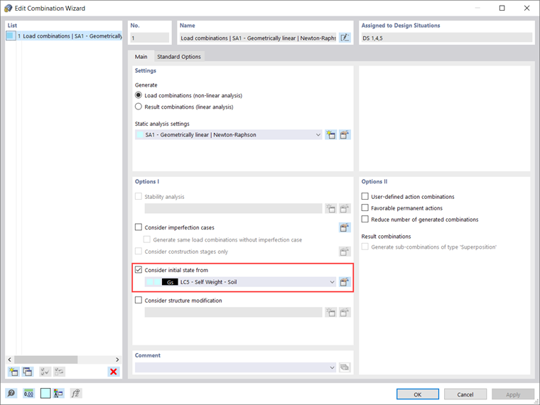
Furthermore, you can adjust the settings of the combination wizard for this design situation. There are multiple options to be defined, as shown in Image 9. What is important at this point is the option to consider the initial state from a load case, which in this example is the Self-Weight Soil load case. This way, all the load combinations generated with the wizard will consider this load case as an initial state.
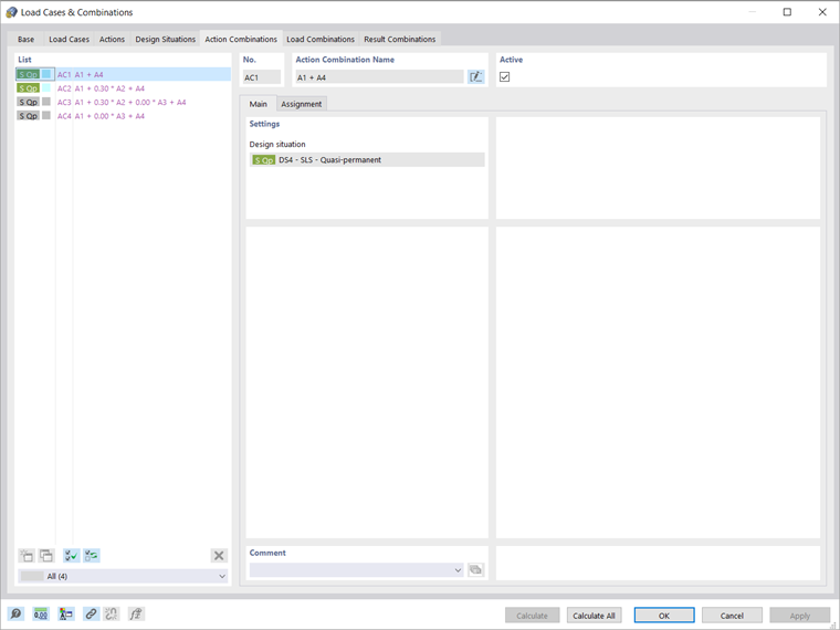
The action combinations that were created automatically are shown in the Action Combinations tab (Image 10). In this particular case, there are four action combinations but only two of them are considered. This is due to the fact that some combination coefficients for the combinations in grey are zero; therefore, they combine the actions in the same manner as the active combinations.
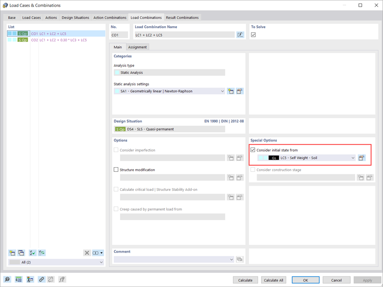
It is possible that you are checking the load combinations that were automatically created by the load combination wizard (Image 11). Please note that the consideration of the initial state is already active as a special option, since we previously did this through the settings of the combination wizard in the Design Situations tab (Image 9).
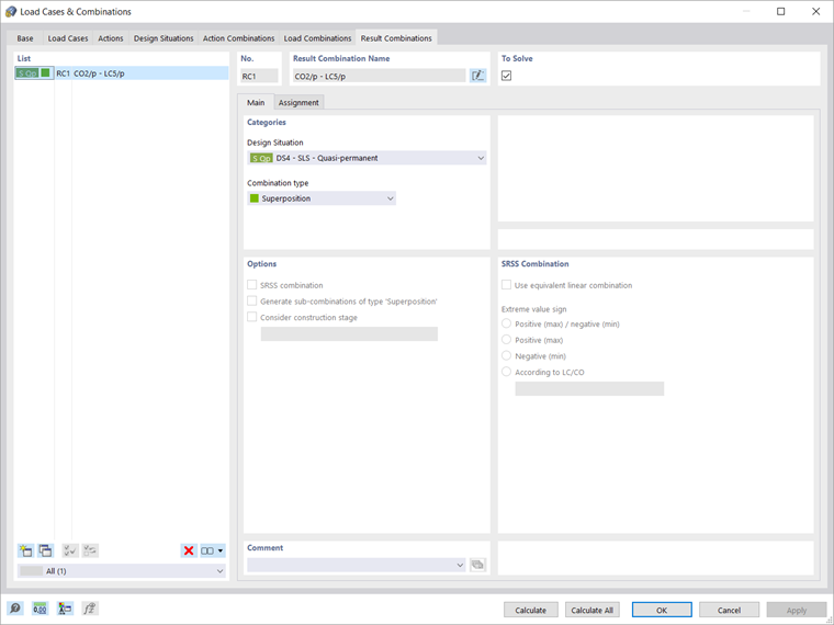
Finally, you can define the result combinations in the associated tab of the Load Cases & Combinations window. The “Design Situation” describes the normative specifications according to which the load cases are combined. As already mentioned, the design situation of interest is the quasi-permanent situation; therefore, it should be selected when defining a new result combination, as shown in Image 12.
The “Combination type”, on the other hand, controls the criteria for superimposing the results. In this example, we are interested in determining the sum of all the results; hence, you should select “Superposition” as the combination type. This means that all load cases and combinations included in the combination are always taken into account and added individually, and there are no maximum or minimum values.
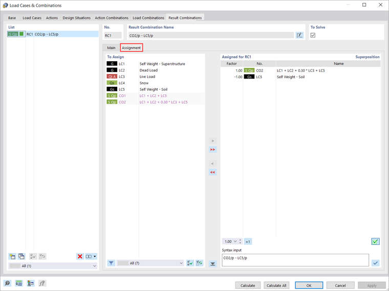
You can assign the load cases in result combinations in the Assignment tab where all available load cases, load combinations, and result combinations are listed in the “To Assign” column. To do this, you have to transfer the entry of interest from this column to the “Assigned for RC” list, as shown in Image 13.
For each entry, you can adjust the factor with which the entry will be considered in the combination. In this example, we are interested in the results associated with the superstructure only; therefore, we must substructure the results associated with the initial state – that is, the “Self-Weight Soil” load case. Hence, the leading load combination is taken into account with factor 1, whereas a combination factor of -1 is assigned to the initial state (that is, the “Self-Weight Soil” load case).
Once the load cases, load, and results combinations are defined, you can start the calculation. If you only want to calculate the results of the current load case or combination, select "Calculate Current Loading" in the "Calculate" menu, or use the “Show Results” button.
If, however, you want to calculate all load cases, combinations, and design situations, select "Calculate All”. This way, RFEM calculates all load cases, load combinations, result combinations, and design situations for which input data are available. The calculation is performed in parallel using several computation cores, and the results are available as shown in Image 14. The results will be discussed in more detail in an upcoming Knowledge Base article.