RFEM applies the Direct Strength Method (DSM) to calculate the elastic buckling load of the member. The Direct Strength Method offers two types of solutions, numerical (Finite Strip Method) and analytical (Specification).
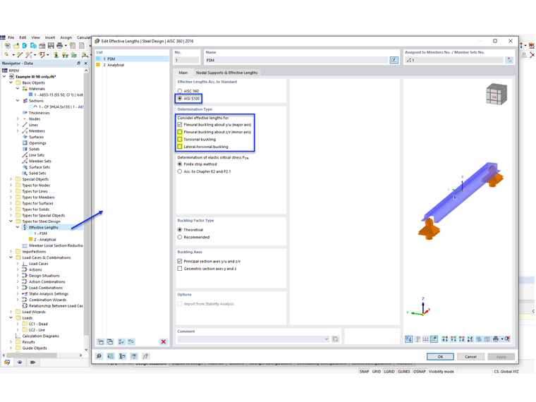
Local and distortional buckling are always calculated using the Finite Strip Method (FSM). For global buckling, the user has the option to select either the numerical method (Finite Strip Method) according to Appendix 2.2 or the analytical method (Chapter E2 and F2.1) according to Appendix 2.3 in the Effective Lengths dialog box (Image 02). For arbitrary sections, it is recommended to use the numerical solution [2].
Example
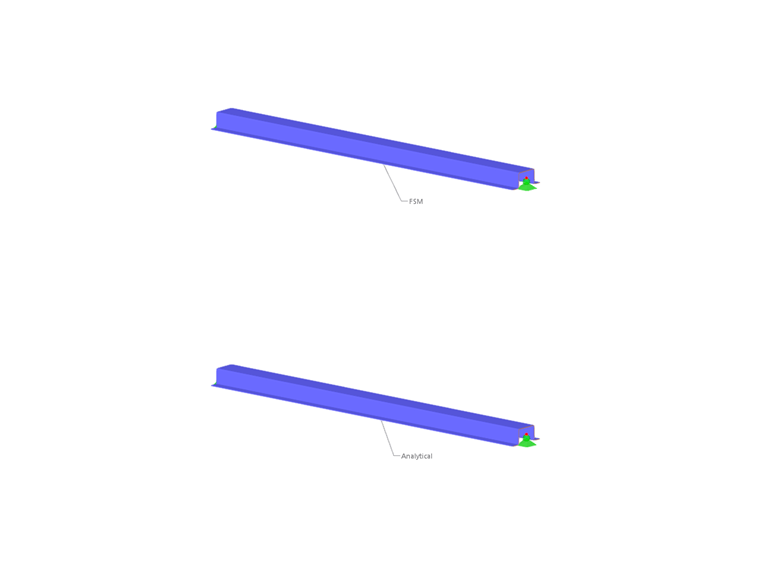
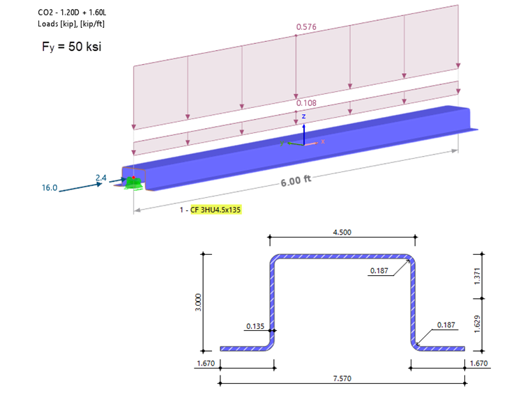
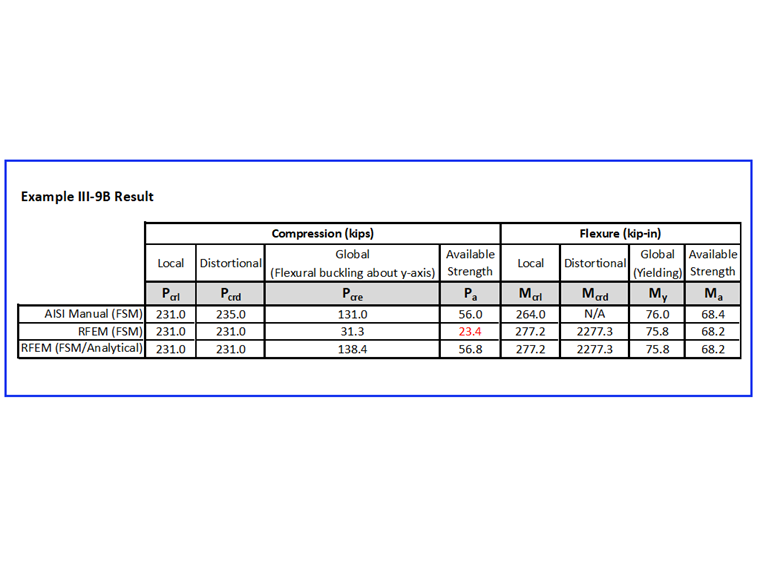
Example III-9B of the AISI manual [3] is used to compare the results obtained from the RFEM model. Two members with the same section and loading are modeled to examine the difference between the numerical (FSM) and the analytical method.
Effective Lengths
The 6 ft long beam-column is continuously braced against lateral and torsional movement, but is free to buckle about the local y-axis (weak-axis bending). Therefore, the option to check for flexural buckling about the z-axis, torsional buckling, and lateral-torsional buckling (LTB) can be deactivated (as shown in Image 02). However, a warning message WA1001.00 will appear for the Finite Strip Method after running the calculation.
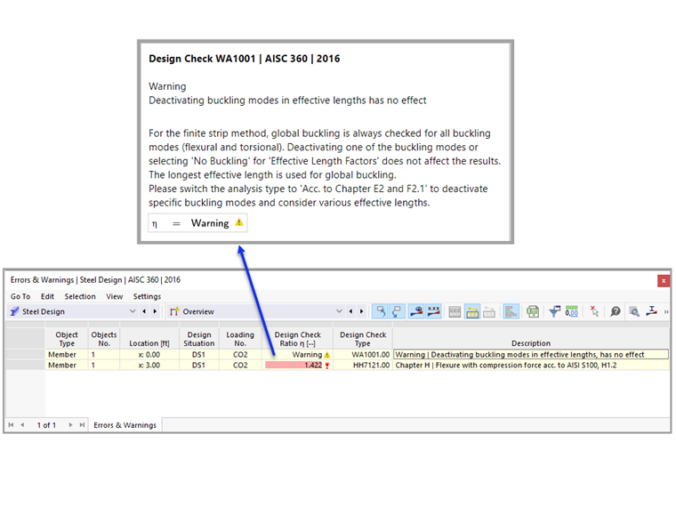
The FSM compressive global buckling check is always based on all possible buckling modes (flexural, torsional, flexural-torsional). The ability to specify restraint for each buckling mode is currently not available in RFEM. In addition, the longest effective length, KL is used for all buckling modes to determine the elastic global buckling strength, Pcre.
To deactivate specific stability checks and to consider various effective lengths, the analysis type “Acc. To Chapter E2 and F2.1” should be selected.
Buckling Shapes
The FSM signature graph can be viewed under Sections. The drop-down menu lists 7 types of buckling shapes including compression as well as positive and negative weak-axis bending, strong-axis bending, and torsion (Image 05).
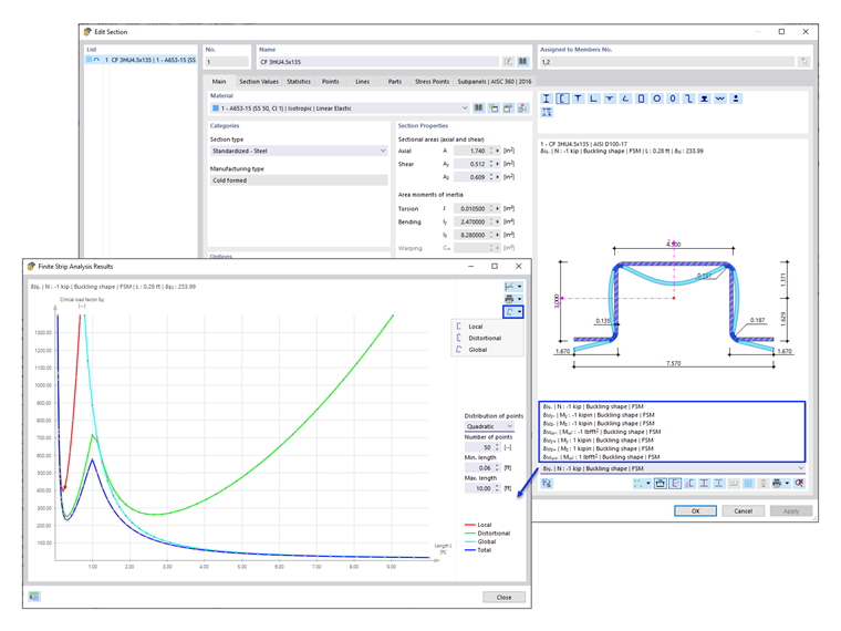
In an ideal scenario, the signature (total) curve can provide the buckling modes of the member immediately. Local buckling is the first minimum in the signature curve, distortional buckling is the second minimum in the signature curve, and global buckling is the final descending branch of the signature curve and can be read directly at the global buckling effective length, KL [2].
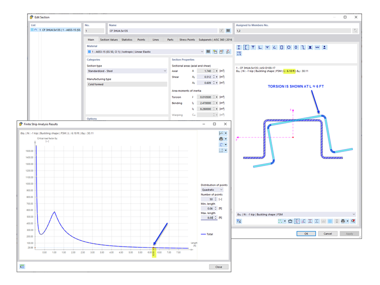
In this example, only the first minimum (local buckling) is apparent in the first mode. The section buckling shape shows that torsional buckling is the controlling buckling mode at 6 ft long. This can be viewed by selecting a point in the graph around the 6 ft length (Image 06). The second minimum (distortional buckling) shows up in the second mode (not available in RFEM).
Compressive Strength
The available compressive strength, Pa is taken as the smallest of the values according to the following AISI sections:
- Section E2 – Yielding and Global Buckling
- Section E3 – Local Buckling Interacting with Yielding and Global Buckling
- Section E4 – Distortional Buckling
The critical elastic buckling loads (Pcrl, Pcrd, Pcre) required to determine the available compressive strength, Pa are presented below.
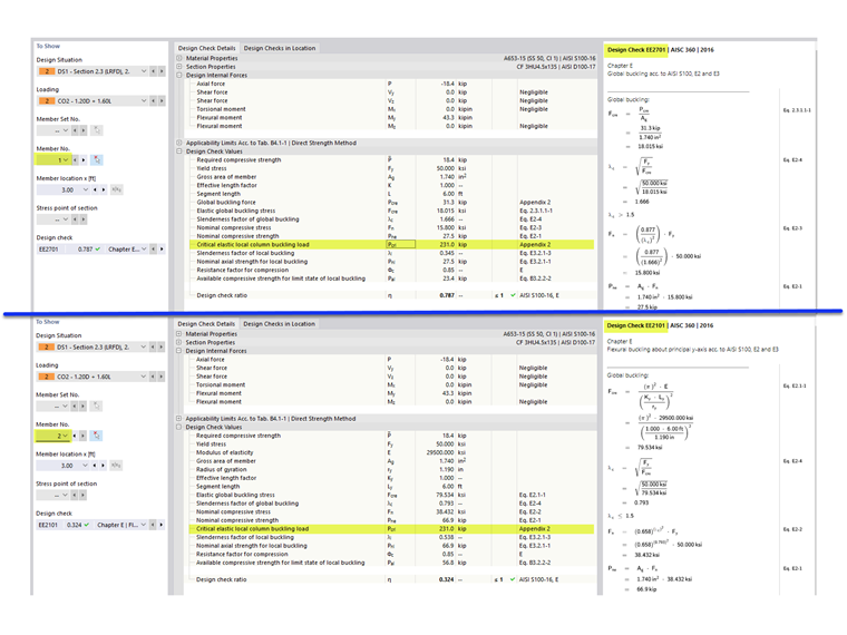
Pcrl (Local)
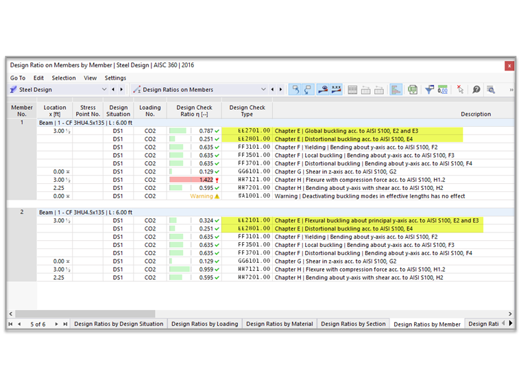
The critical elastic local column buckling load, Pcrl is shown under the global buckling design checks EE2701.00 (FSM) and EE2101.00 (Analytical). Pcrl equals 231 kips is taken from the FSM total curve (shown in Image 05). As previously mentioned, the local buckling is always calculated using the FSM. This value agrees with what is shown in the AISI example.
Pcrd (Distortional)
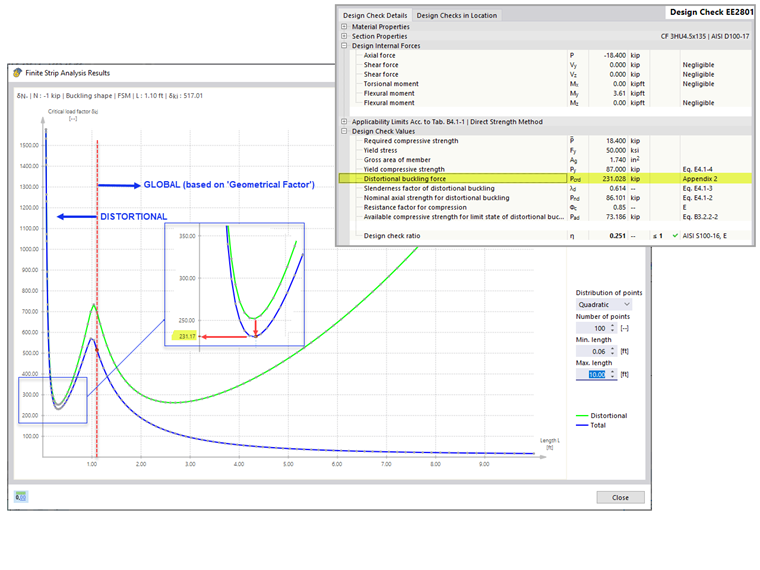
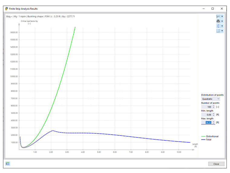
The critical elastic distortional column buckling load, Pcrd is shown under design check EE2801.00 for both methods. Pcrd equals 231 kips is taken from the FSM graph. In a case where the second minimum is not apparent on the total curve, the distortional curve is used to identify the appropriate length along the horizontal axis. From there, the location is projected to the total curve to obtain the critical load factor (Image 09).
The 231 kips at 0.32 ft length is the last relevant minimum on the distortional graph. Buckling shapes beyond this length are categorized as global buckling. RFEM applies a “geometrical factor” to characterize the buckling shapes as global or distortional. This value is close to the 235 kips listed in the AISI manual.
Pcre (Global)
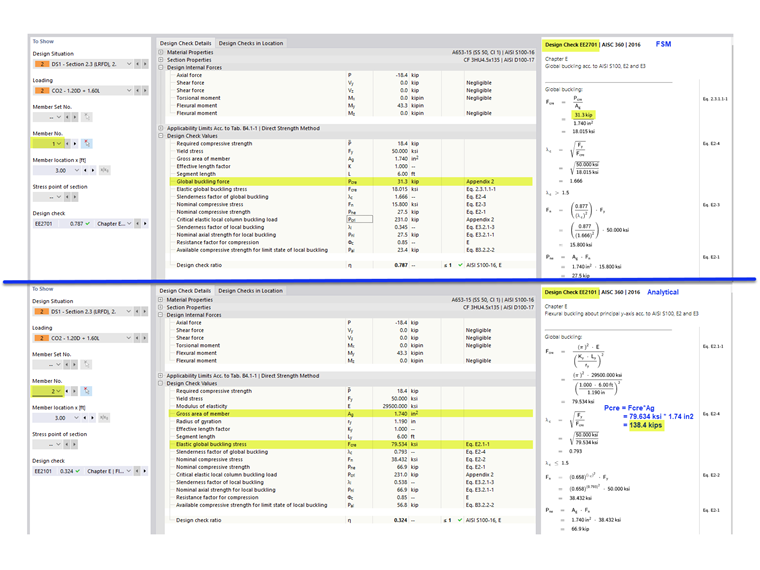
The elastic global (flexural, torsional, flexural-torsional) buckling load, Pcre is shown under design check EE2701.00 (FSM). Under design check EE2101.00 (analytical), Pcre is simply determined from multiplying the stress by the area, Fcre x Ag (Image 10).
Flexural Strength
The available flexural strength, Ma is taken as the smallest of the values according to the following AISI sections:
- F2 Yielding and Global (Lateral-Torsional) Buckling
- F3 Local Buckling Interacting with Yielding and Global Buckling
- F4 Distortional Buckling
Mcrl (Local)
The critical elastic local buckling moment, Mcrl is shown under the design check FF3501.00 for both methods. Mcrl equals 277 kip-in is close to the 264 kip-in value shown in the AISI example.
Mcrd (Distortional)
From evaluating the distortional curve, it can be seen that the critical distortional buckling moment is extremely high and unlikely to be the controlling mode. In the AISI example, it was determined that the section is not subject to distortional buckling, “Reviewing the characteristic curve and corresponding mode shapes generated from the finite strip analysis, it is observed that this section is not subject to distortional buckling” [3].
Mcre (Global)
Since the member is fully braced against global (lateral-torsional) buckling, yielding controls. The available flexural strength, Ma equals 68 kip-in are the same for both methods and also agree with the AISI example.
Summary
Conclusion
Local and distortional buckling are always calculated using the Finite Strip Method (FSM). For global buckling, the numerical method (Finite Strip Method) and the analytical method (Specification) are available.
In a case where the second minimum is not apparent on the total curve, the distortional curve is used to identify the appropriate length along the horizontal axis. From there, the location is projected to the total curve to obtain the critical load factor (Image 09). Additionally, RFEM applies a “geometrical factor” to characterize the buckling shape as global buckling or distortional buckling when both modes are present.
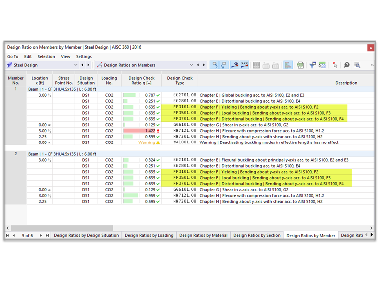
In the above example, the available compressive strength, Pa equals 23.4 kips is conservative yet inaccurate since it is actually based on torsional buckling (instead of flexural buckling about y-axis). A warning message (shown in Image 04) presented by the program suggests the use of the analytical method when not all of the buckling modes are applicable.
A good practice is to review the signature curve of the section and its corresponding buckling modes to verify the validity of the result. In general, it is recommended to use the Finite Strip Method and compare the results with the analytical solution according to Chapter E and F.