


In addition to the requirements regarding the load-bearing capacity, proper requirements for the serviceability of a structure must be met. In this context, the design check of deformations plays an important role in order to prevent damage due to excessive deflection. Corresponding rules can be found in various standards.
The displacements' limit values are usually related to the lengths of the structural components; for example, according to EN 1993 [1] or AISC 360 [2] for steel structures, according to EN 1992 [3] or ACI 318 [4] for reinforced steel structures, and according to EN 1995 [5] or NDS [6] for timber structures. In Chapter L2. DEFLECTIONS of AISC 360, for example, we can find the following rule: "Deflections greater than 1/200 of the span may impair operation of movable components such as doors, windows, and sliding partitions." For each material, there are also different limit values to be applied for the span and cantilever areas of beams.
RFEM and RSTAB allow you to control the displacements in the design checks and to give them out as a design.
Example
The model of a simple wooden platform shows how to proceed with the deflection design check. It represents a grillage consisting of glued-laminated timber members, which is subjected to three load cases: self-weight, live load of the platform, and live load of the cantilever area. The superposition of load cases is carried out according to EN 1990 [7] taking into account the specific requirements for timber structures such as creep; the design check is performed according to EN 1995-1-1 [5]. The stability is not analyzed in the ultimate limit state design. The design of the deflection in the serviceability limit state is carried out for the quasi-permanent design situation.
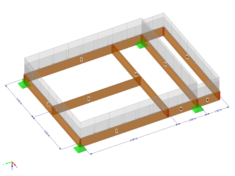
The platform is a symmetrical structural system. In the model, however, the edge beam is shown as a completely continuous member with nodes of the "On Member" type on one side, and on the other side as individual members.
The Timber Design add-on is activated for the design checks. The design is carried out according to EN 1995, including CEN recommendations.
Serviceability Configuration
Since the deflection design check is carried out for the serviceability limit state, you have to select the Serviceability option in the configurations to be calculated for the timber design. These settings are managed in the "Global Settings" dialog box, which you can access on the shortcut menu of the "Timber Design" navigator entry.
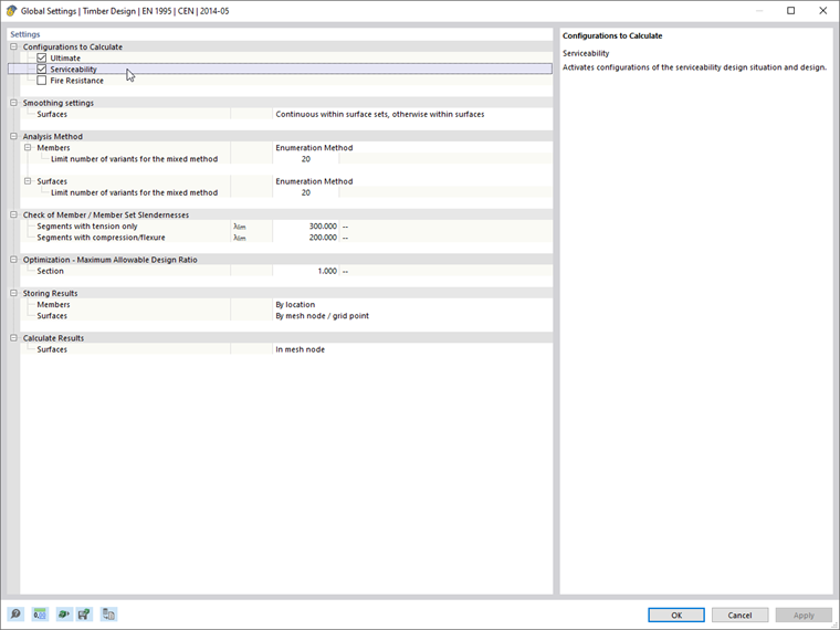
The fire resistance should not be analyzed.
The limit values of the deflections are stored in the Serviceability Configuration, which is created as a standard when activating the timber design.
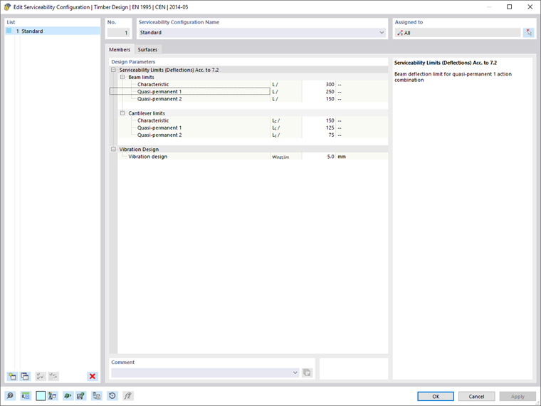
The serviceability limits are set by default according to the standard, but can be adjusted. Separate specifications are possible for beams (bending members supported on both sides) and cantilevers (bending members supported on one side), which apply depending on the design situation. Two criteria are provided for the quasi-permanent design situation. Due to this provision, the requirements for the net final deflection wnet,fin and the final deflection wfin according to [5] Table 7.2 are fulfilled.
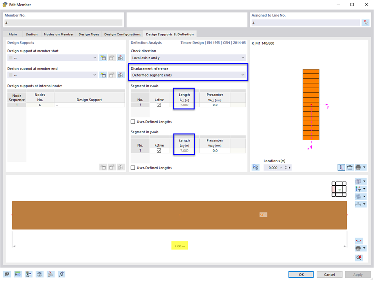
Deflection Analysis
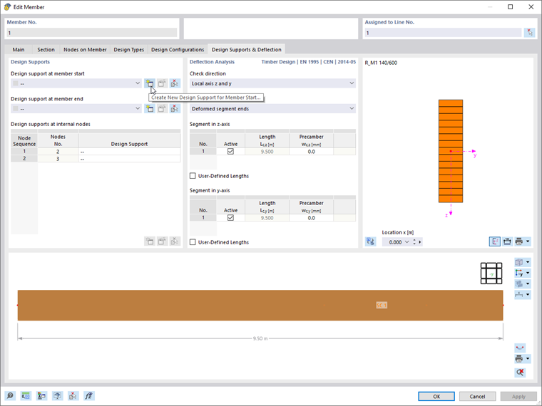
The specifications for the deflection analysis should be made separately for each member. By default, the displacement is related to the total length of the member and the deformed member ends. The specifications are stored in the Design Supports & Deflection tab of the "Edit Member" dialog box.
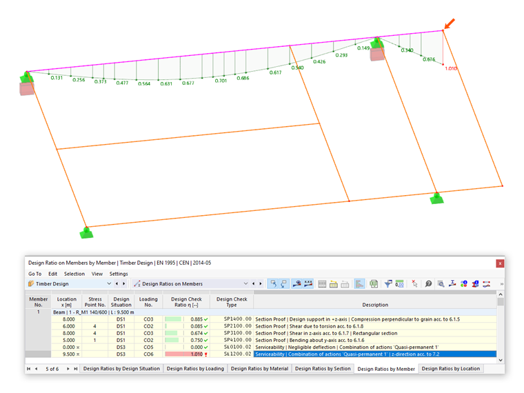
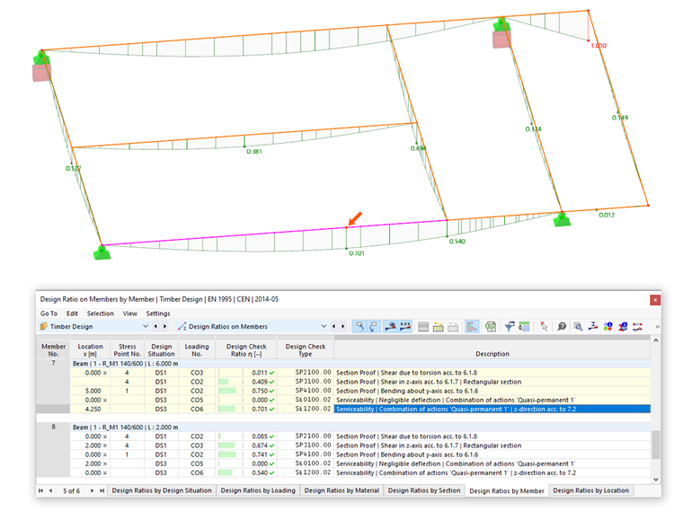
If the model is designed by these standard settings, the design ratios shown in the following image are the result for the deflection analysis.
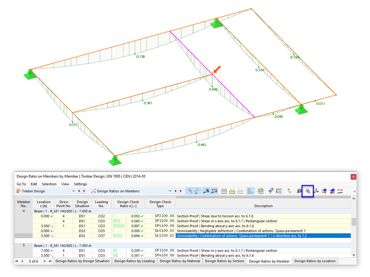
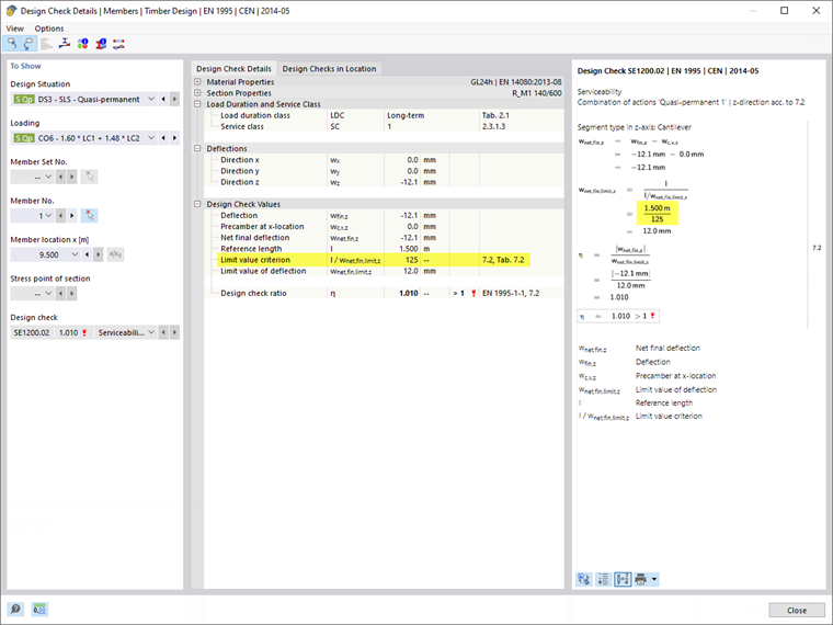
For example, for Member 4 (transverse beam between longitudinal members), these default settings are correctly applied: In case of a deflection in the member middle, you need to consider the deformation of the edge beams. Use the design check details that you can access for the corresponding design point by clicking the button
![]() (see the image above) to understand the determination of the design criterion.
(see the image above) to understand the determination of the design criterion.
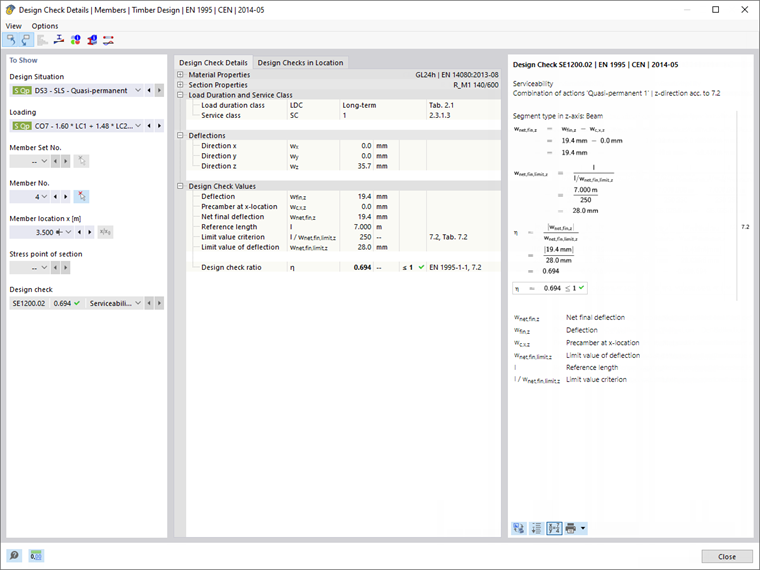
The governing deformation of the transverse beam for the quasi-permanent design situation is 35.7 mm in CO 7. If this value was used for the design check, it would be greater than the limit value of L/250 = 7,000 mm / 250 = 28 mm. At the member ends of the transverse beam, the edge beams have a displacement of 16.2 mm each in CO 7, which need to be taken into account in the design check: 35.7 mm - 16.2 mm = 19.5 mm (the program considers even more decimal places).
The design criterion uses the local deformation related to the straight line connection of the end nodes. It results in 19.5 mm / 28 mm = 0.69. Thus, the member's local deformation value is reduced if its end nodes are displaced. This approach is correct for the transverse beam, as well as for most of the members in the example – with the exception of the two edge beams.
Design Support
As shown in the Result Determined by Standard Settings image, the design criterion for the continuously modeled edge beam (Member 1) is not correct: It represents a continuous deformation that does not take into account either the intermediate support or the cantilever. Manual adjustments are necessary here.
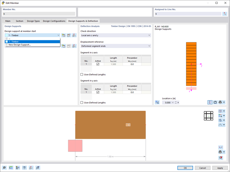
Since the edge beam is modeled by nodes of the "On Member" type, the boundary conditions of the extracted system can be represented by using Design Supports. They make it possible to arrange internal supports and to model free ends. The node at the supported member end represents the member start; the node on the cantilever represents the member end.
The "internal nodes" of the continuous member are identified. It is assumed to be a single "Segment". Since it does not correspond to the model, some supports need to be assigned. In the "Design Supports & Deflection" tab, click the
![]() , button to define a "Design support at the member start".
, button to define a "Design support at the member start".
The "New Design Support" dialog box appears.
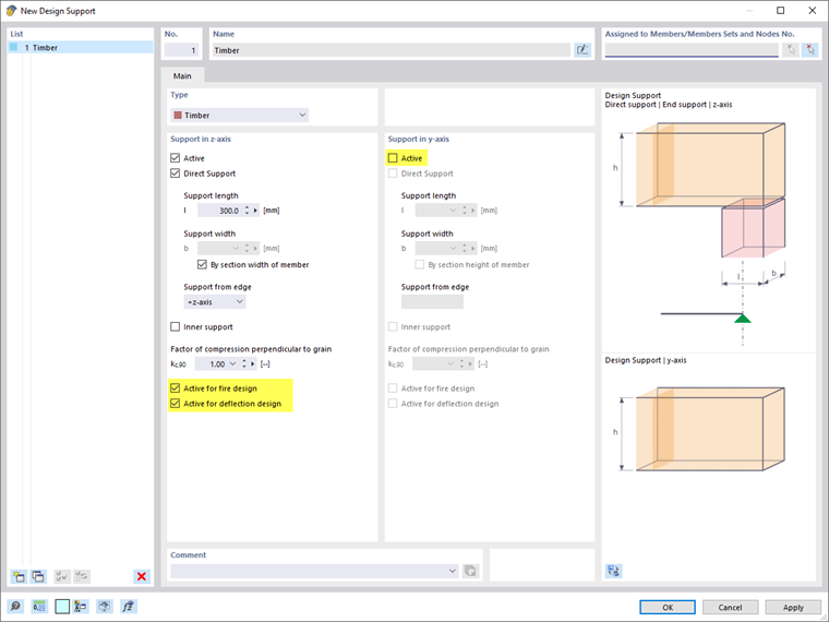
With the "Timber" type already preset, the specifications for timber design can now be entered. There is a "Direct Support" at the nodal supports. A support length of 300 mm is assumed; the width of the support should correspond to the width of the beam. In order for the support to be taken into account in the design check, it is necessary to select the Active for deflection design option. The "Support in y-axis" can be deactivated, since the support at right angles to the member is not relevant for the model.
Click OK and then assign the design support to the member start and the second internal node (the first inner node is the connection point of the transverse beam).
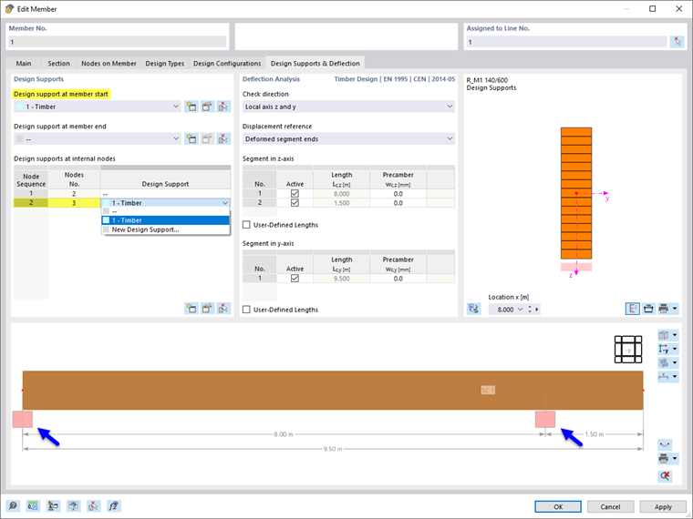
Now, two segments are available on the member model; one with a length of 8.00 m, and the other with a length of 1.50 m.
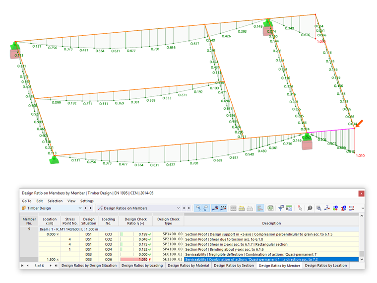
The design check applying the changed boundary conditions provides the following result:
The reference lengths and limit values for the span and the cantilever area are now correctly set in accordance with the standard. You can check this again in the design check details.
User-Defined Lengths and Displacement Reference
The second edge beam is modeled by three adjoining individual members. Here, again, manual adjustments are necessary so that the design checks are not performed based on the single members (see the image Result Determined by Standard Settings).
Member 7 and Member 8 represent the "span area" of the beam having a support on both sides. The segment length is preset by the member length. However, since the segment corresponds to the total length of the two members, you need to specify the length manually here: Select the User-Defined Lengths check box ❶ and then set the "Length" of each segment to 8.00 m ❷. This value corresponds to the support length between the support points (see the image Model of Timber Platform).
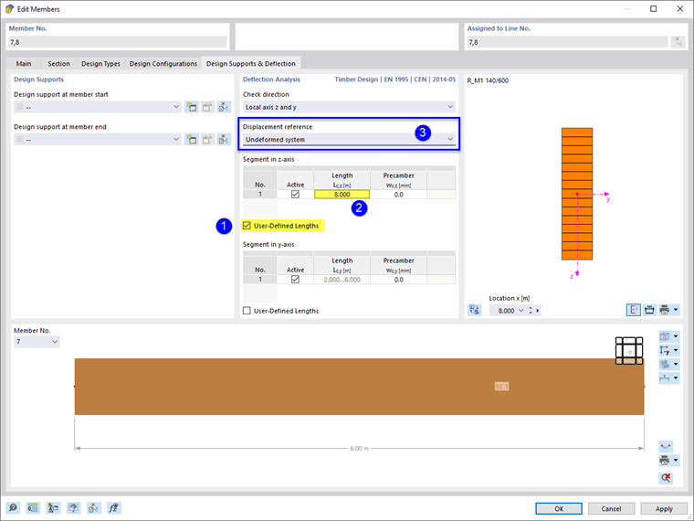
In this case, the deflection should not be related to the deformed segment ends, otherwise the program would use the connection line between the support node and the displaced connection node of the transverse beam as a reference. Therefore, select the "Undeformed system" option in the Displacement reference list ❸.
Design supports are not required, as a bilateral support is automatically assumed. The design check applying the changed specifications provides the following result:
Cantilever
Finally, an adjustment is required for the cantilever area of the second edge beam (Member 9). Since the program automatically assumes a bilateral support, as mentioned, you need to define the structural support manually for this case. Assign a Design Support to the member at the member start by selecting the previously defined "Timber" type in the list.
The free end of the member should remain without a design support. The final design check now provides identical design criteria for both edge beams.
Conclusion
The example presents various options on how to proceed when designing deformations in RFEM or RSTAB. Bending beams with supports on both sides do not require special attention, as the program automatically identifies the boundary conditions. With the default setting for the reference of the displacements to the deformed segment ends, the displacements of the overall system are correctly taken into account in the design check.
In the case of divided members, however, it may be necessary to adjust the support length manually and to relate the displacement to the undeformed system. In the case of continuous members and cantilevers, design supports have to be assigned in order to correctly represent the support conditions of the extracted model.
