21 Results
View Results:
Sort by:

In RFEM 6 it is possible to define multilayer surface structures with the help of the “Multilayer Surfaces” add-on. Hence, if you have activated the add-on in the model’s Base Data, it is possible to define layer structures of any material model. You can also combine material models of, for example, isotropic and orthotropic materials.

You can model and analyze masonry structures in RFEM 6 with the Masonry Design add-on that employs the finite element method for the design. Complex masonry structures can be modeled, and static and dynamic analysis can be performed, given that a nonlinear material model is implemented in the program to display the load-bearing behavior of masonry and the different failure mechanisms. You can enter and model masonry structures directly in RFEM 6 and combine the masonry material model with all common RFEM add-ons. In other words, you can design entire building models in connection with masonry.

In this article, the adequacy of a 2x4 dimension lumber subject to combined biaxial bending and axial compression is verified using the RF-/TIMBER AWC add-on module. The beam-column properties and loading are based on example E1.8 of AWC Structural Wood Design Examples 2015/2018.

In the "Edit Load Cases and Combinations" dialog box, you can combine different load cases in one load combination under the "Load Combinations" tab.

This article deals with elements concerning which the cross-section is subjected simultaneously to a bending moment, a shear force, and an axial compressive or tensile force. However, in our example we will not include loading due to shear force.

This article describes how a flat slab is generated as a 2D model in RFEM and the loading is applied according to Eurocode 1. The load cases are combined according to Eurocode 0 and calculated linearly. In the RF-CONCRETE Surfaces add-on module, the bending design of the slab is performed while taking into account the standard requirements of Eurocode 2. The reinforcement is complemented by a rebar reinforcement for areas that are not covered by the mesh basic reinforcement.
![[Edit Parameters] Button in Table Toolbar](/en/webimage/009362/2418341/01-en-png.png?mw=640&hash=c76563b459152b19c98197ea6ba342be89d9a5bc)
The SHAPE‑THIN stand-alone program determines the characteristic values and stresses of any thin‑walled cross‑sections. Graphic tools and features allow for modeling complex cross‑section shapes. In addition to the graphical input, it is also possible to enter the data in tables. As an alternative, you can import a DXF file and use it as a basis for further modelling. Also, each cross-section can be entered using the cross-section library of Dlubal Software and combined as a part with the user-defined elements.
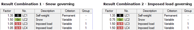
My previous article Result Combinations 1 explained the basic principles of result combinations on simple examples. This article describes a further application case that combines the definition options of Examples 1 and 2. Likewise, the effort should be compared to a combination by means of load combinations.
![Parameters of Effective Slab Width (Figure 5.3 [1])](/en/webimage/009561/2419376/01-en-png.png?mw=640&hash=c76563b459152b19c98197ea6ba342be89d9a5bc)
In the case of combined FEM structures (surface and member elements) as well as folded plate structures, it is possible to attribute a beam structure for the design on a member to a fictitious T-beam cross-section, whose geometry depends on the effective width. When using the "Rib" member type in RFEM, the stiffness is represented by a slab component (surface element) and a web component (member element). This approach has some design specifics that are explained in this article.
RFEM and RSTAB provides two different methods for the superposition of load cases. Using load combinations, the loads of individual load cases are superimposed and calculated in a "big load case". On the other hand, result combinations only combine the results of the individual load cases. This article describes the with the basis of defining result combinations and explain it in detail on two examples.
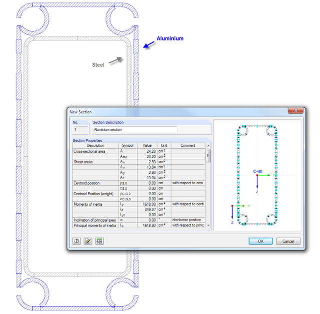
SHAPE‑THIN cross‑section properties software provides the option to combine cross‑section parts in a "section" and display the cross‑section properties. Thus, you can determine the values of the individual components in a composite cross‑section.
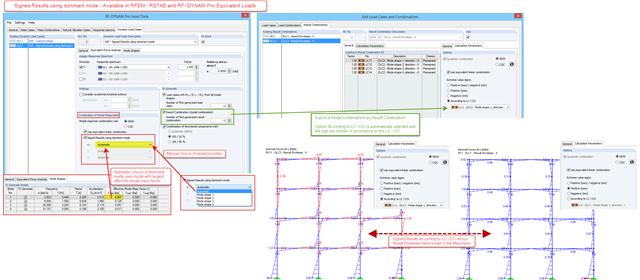
In RF-/DYNAM Pro – Equivalent Loads, a signed result option in accordance with the dominant eigenmode has been available since version X.06.3039. For the modal combination of results corresponding to the single eigenvalues, a quadratic combination rule has to be used. In RFEM and RSTAB, the SRSS and the CQC rule are available. Only results, not loads, are allowed to be combined directly. The reason is the mode shapes, which are arbitrarily scaled and signed.
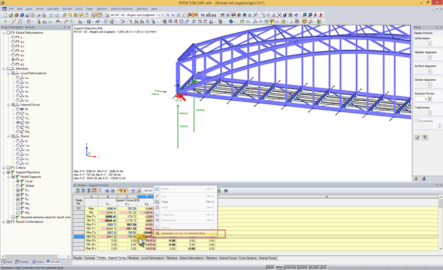
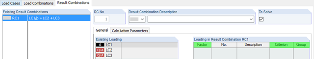
A result combination (RC) combines results from the selected load cases (LC), load combinations (CO), and result combinations according to a preset combination syntax. Since a particular result may show an extreme value, depending on the combination at various locations of the structure, the RC displays the maximum and the minimum values for each result type.
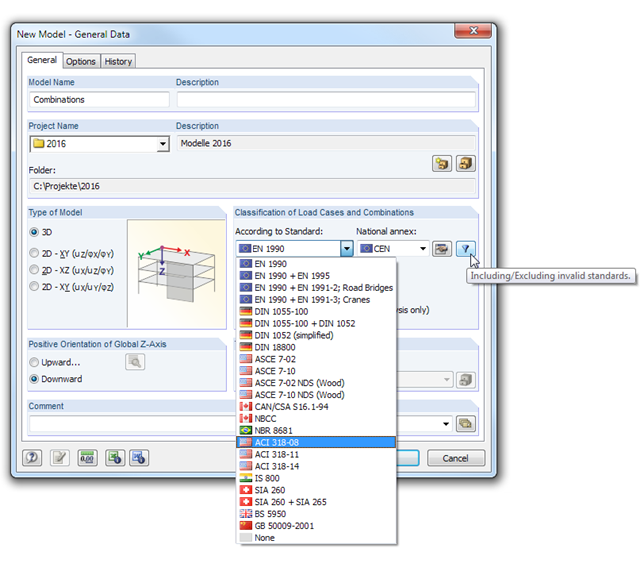
In RFEM and RSTAB, load cases can be combined automatically using combination coefficients (partial safety factors) in order to determine the required design situations.
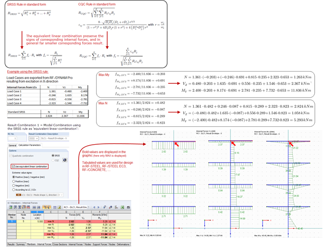
The modal results of a response spectrum analysis are combined with quadratic combination rules, and in RF‑/DYNAM Pro, the SRSS and the CQC rules are available. The default setting modifies the quadratic expressions into equivalent linear combinations. The advantage of this option is that the corresponding internal forces keep their signs and are often much smaller, compared to the standard SRSS or CQC rules. The standard SRSS and CQC rules are on the conservative side and the "equivalent linear combinations" are recommended.
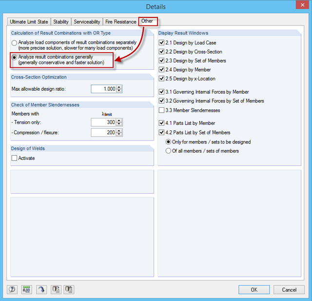
You can obtain many load combinations, especially when using the automatic generation of combinations. These are automatically combined in a result combination (RC) with the OR operator as an envelope. Then, if you select one RC for design in RF‑/STEEL EC3, it may lead to a very long calculation time because the module calculates all combination options individually by default, then displays the results of the governing combination.

In January 2015, DIN Committee NA 005‑08‑23 Steel Bridges applied the introduction of a modification in equation 10.5 of DIN EN 1993‑1‑5. This involves the interaction of longitudinal and transverse pressure in a buckling analysis. Now, the interaction equation provides for auxiliary factor V, which is calculated from the reduction factors of the longitudinal and transverse stresses.
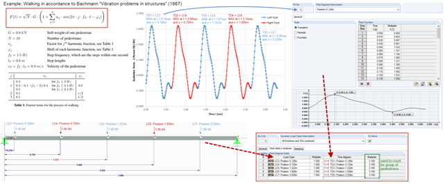
To simulate an excitation that varies over time and changes its position, you can combine several loading time diagrams in RF‑/DYNAM Pro - Forced Vibrations.
RF-LAMINATE allows free definition of materials. Thus, you can combine any compositions of different materials. The combination of concrete and timber is possible as well. However, the rigid composite must be provided when defining such a composition. In RF-LAMINATE, you can consider full shear coupling or no shear coupling at all.
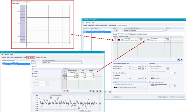
In RF-/DYNAM Pro - Forced Vibrations, you combine static load cases with time diagrams to define the type of excitation of your structure. This way, you can use not only nodal loads, but also use line, surface, free, or generated loads in the time history analysis.
When defining real support conditions, it is always necessary to combine linear and nonlinear support conditions. This way, a beam resting on a wall can transfer compression forces to the wall and the line support (wall) will not take over the lifting forces. These forces should be carried by screws, for example, which are defined as a linear nodal support.