


Effective width
In the case of bending stress and a compression zone on a slab side, it is assumed that the slab participates in the load bearing effect. The effective width is a geometric size, which can be used for the application of approximately constant, maximum concrete compression stress.
The rib defined in RFEM is transferred to the RF-CONCRETE Members add-on module in such a way that beff,i = bi is set.
![Parameters of Effective Slab Width (Figure 5.3 [1])](/en/webimage/009561/2419376/01-en-png.png?mw=760&hash=7ec548270c812e4679005b311ca774da4860d51a)
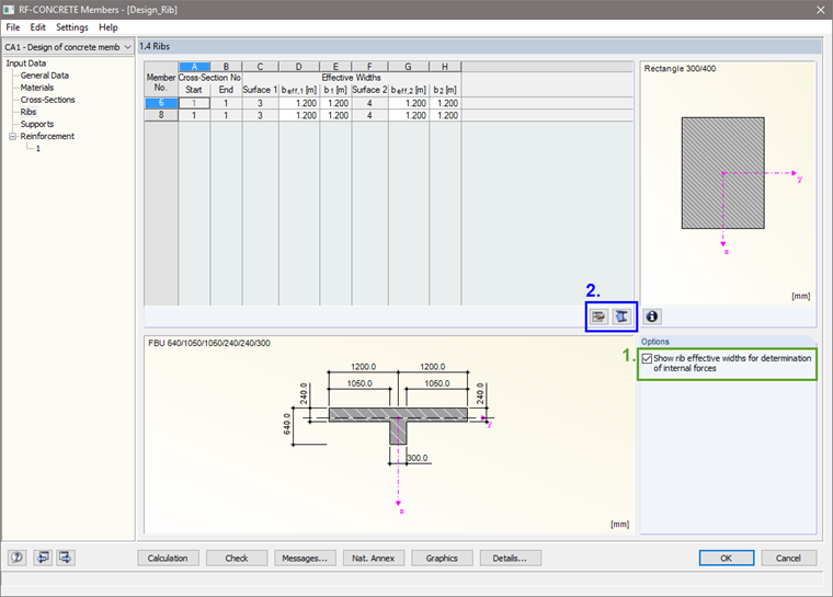
If beff,i does not correspond to bi, a user-defined adjustment is possible. Generally, the effective width beff,i is a size that is not determined automatically in the program and thus has to be specified by the user. The effective widths can be adjusted in Window 1.4 of RF-CONCRETE Members after selecting the check box "Show rib effective widths for determination of internal forces" (see Figure 2).
Both the integration width and the effective width can only be constant in RFEM for each member. This corresponds to the requirements of EN 1992-1-1 provided in Section 5.3.2.1 (4). If special accuracy is required for the determination of internal forces, it would be necessary to split the downstand beam into individual members, depending on the different areas of the effective widths.
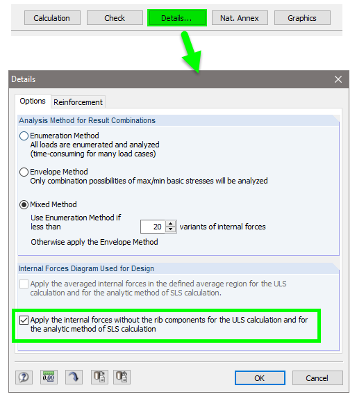
If the rib is designed in RF-CONCRETE Members and the structure is to be designed additionally in RF-CONCRETE Surfaces, the internal forces considered in the member design by using the integration widths can be neglected in the surface design. The respective setting can be done in Details of the RF-CONCRETE Surfaces module (see Figure 3).
Design for torsion
The torsional resistance is to be distinguished according to its cause.
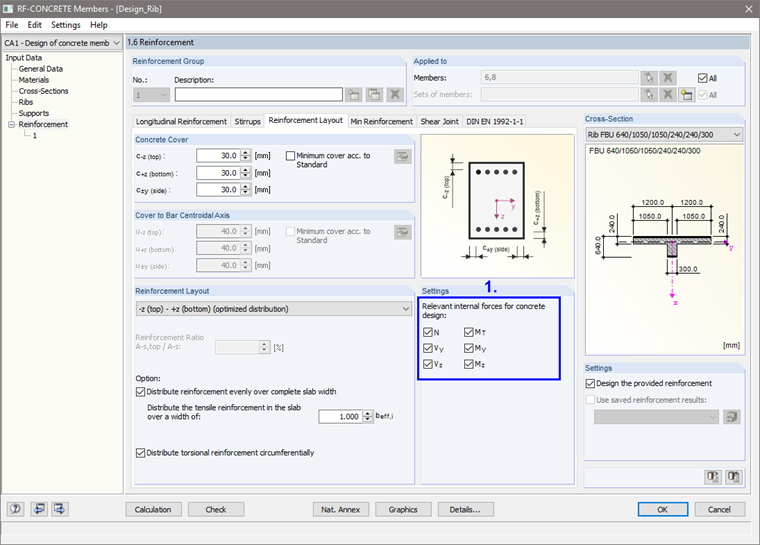
If the torsion in statically indeterminate structures is caused by the compatibility of deformations (compatibility torsion), it is not necessary to perform the torsion design, according to EN 1992-1-1, 6.3.1 (2). Related to this paragraph, MT should not be taken into account for the rib design. You can deactivate MT in Window 1.6 of RF-CONCRETE Members (see Figure 4).
If the torsion is caused by static equilibrium conditions, the torsion design is required; otherwise, the structure without torsional stiffness would be unstable (equilibrium torsion).