Frequently, there is the requirement to create cross-section series, it means the same cross-sections with different dimensions. Parameters allow you to quickly and easily modify the cross-section dimensions. The parameters can be used in formulas to determine a numeric value. You can edit the formulas using Formula Editor. If a parameter is changed in the parameter list, the results of all formulas using this parameter are adapted.
Parameter List
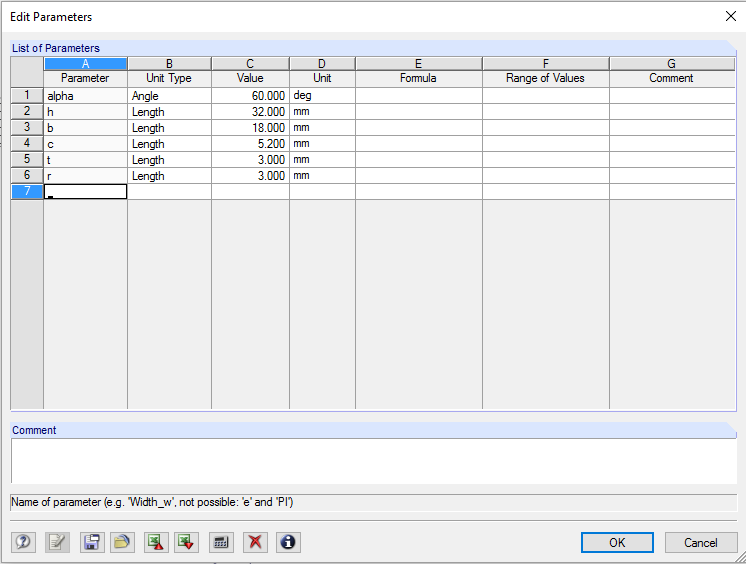
The parameters are managed in the parameter list, which can be opened by clicking the [Edit Parameters] button in the toolbar of the input table or in Formula Editor.
![[Edit Parameters] Button in Table Toolbar](/en/webimage/009362/2418341/01-en-png.png)
![[Edit Parameters] Button in Formula Editor](/en/webimage/009363/2418351/02-en-png.png)
The parameter name (Column A) should not contain any spaces and may only be assigned once. This parameter is used to address the parameter in the formulas.
The parameter is of a certain type (Column B). Distances should only have one parameter of the length type, for example. Depending on the type, the corresponding particular unit (Column D) can be selected.
You can enter the parameter value directly in Column C or define it using a formula in Column E. In addition to the general mathematical operations, the verification is possible using the If and Max/Min functions. The $\$$ reference can refer to a specific table. For example, $\$$1.1(A1) uses the value of Cell A1 in Table 1.1. In Table Column F, you can define a Range of Values to control the values of Column C.
In addition to entering the parameters in the “Edit parameters” dialog box, they can be imported using an Excel file.
Formula Editor
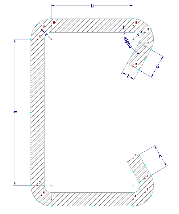
Formula Editor manages the equations of the parameterized input. You can open it by clicking the button in the table toolbar, the yellow or red corner in the table cell, or the function buttons next to the text box in the dialog boxes.
![[Edit Formula] Button in Table Toolbar](/en/webimage/009364/2418361/03-en-png.png)
The formula can be entered in the “Formula” text box. It can include constant numerical values, parameters, or functions. The content of the other cells can be used in formulas via references. A reference starts with an exclamation mark and the reference cell is placed in brackets. For example, !(D2) is the value of Cell D2).
Example
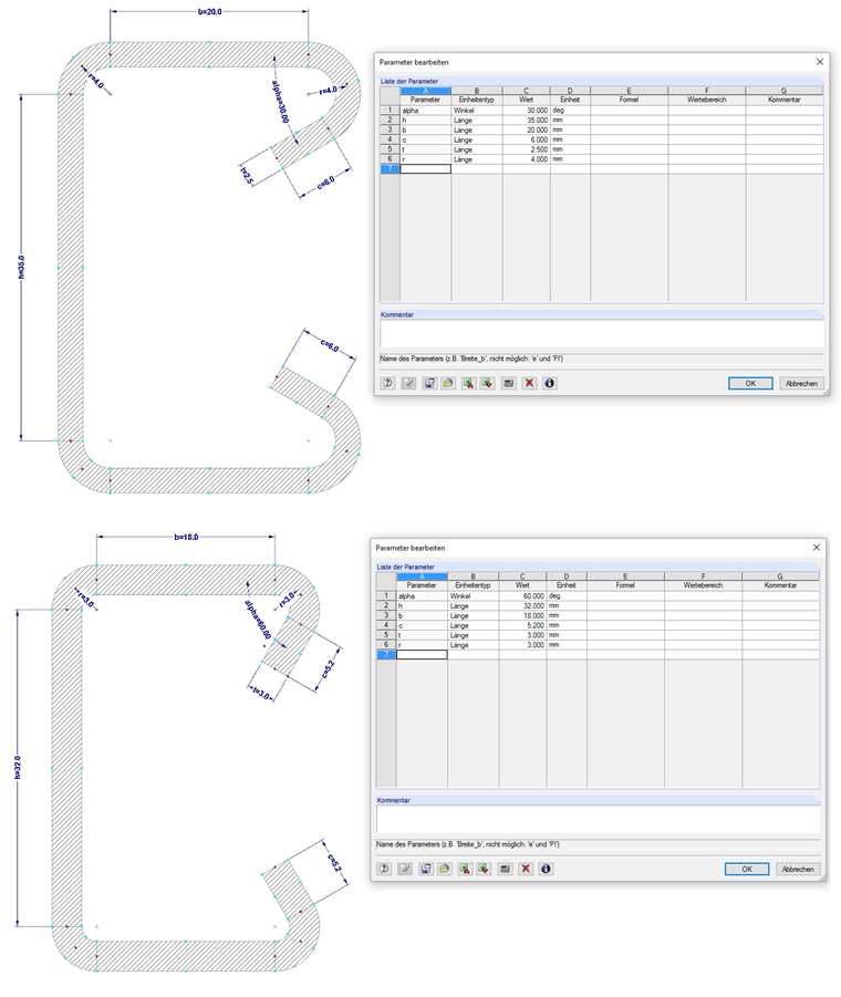
The cross-section shown in Image 06 is to be entered parametrically in SHAPE‑THIN 8.
For this, the parameters shown in Image 07 are defined.
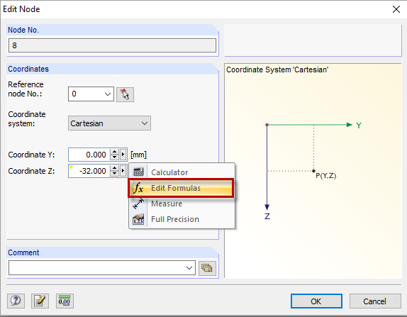
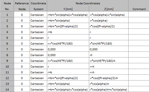
Then, node coordinates can be defined using formulas (see Image 08).
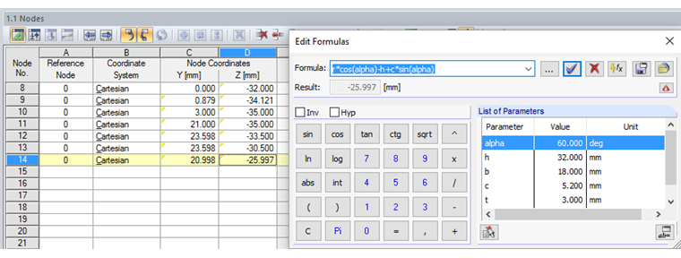
The formulas used are shown in Image 09.
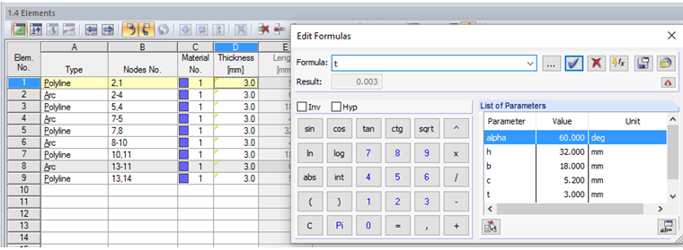
In the next step, the element thickness is assigned using the corresponding parameter (Image 10).
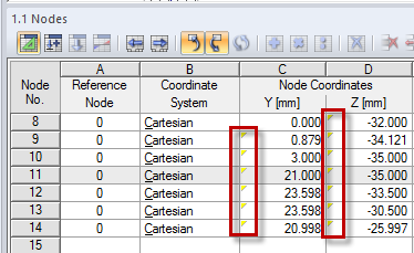
By changing the parameters, the dimensions of the cross‑section can now be adjusted easily (Image 11).