


Basis of the Definition
A combination of load cases using result combinations allows simple addition as well as comparison of the results (either/or). Therefore, the definition of result combinations is more complex than the definition of load combinations and depends largely on "Factor", "Criterion", and "Group".
"Factor" multiplies the results of load cases. Usually, a partial factor or a combination factor is defined here. Positive values mean addition; negative values mean subtraction.
"Criterion" determines whether the results of a load case are always applied in the combination ("Permanent") or have only an occasional effect ("Variable"). Thus, the results of a load case with the "Variable" criterion are only considered in the superposition if they make an unfavorable contribution to the result. Since it is not clear whether the maximum positive or the maximum negative value contributes to the unfavorable result, both values are recorded.
"Group" allows you to set alternative actions of load cases. For example, if two load cases are assigned to the same group, the results of either the first load case or the second load case will be taken into account in the combination.
In the following two examples, result combinations are used for the addition of the results (Example 1) and for finding the maximum and minimum of several load situations with alternative actions (Example 2).
Example 1: Addition of Results
The results of three different load cases are on the same x‑location in the model. Only the normal force (N), shear force (Vz), and bending moment (My) are considered in a simplified way. Load Case 1 includes permanent loads; the other two load cases are imposed load cases.
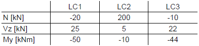
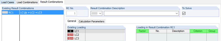
Using the result combination, all three load cases will now be added together. The load cases are defined as follows:
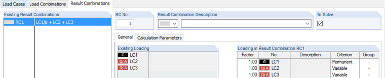
Since Load Case 1 includes permanent loads, the "Permanent" criterion is assigned to it. The imposed load cases may act, but not necessarily. Therefore, this criterion is set to "Variable". Also, both imposed load cases may occur simultaneously. Thus, the group is not defined. To simplify the theoretical recalculation, no partial factors are applied (factor = 1.0).
As a result, you get the maximum value and the minimum value for each internal force. Similarly, the corresponding internal forces are displayed.
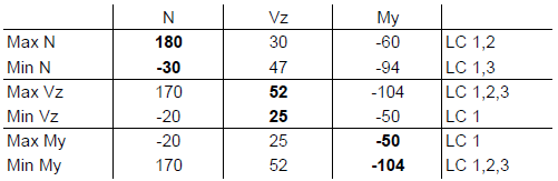
Let us explain the results in more detail in the calculation of the Max N values in the first line. In this case, the basis of the calculation is Load Case 1, as this has been defined as a "Permanent" action. The normal forces of the other two load cases are only used if they increase the normal force. Load Case 2 increases the maximum normal force, while Load Case 3 reduces it again. Therefore, only Load Case 1 and Load Case 2 apply to the maximum normal force:
Max. N = -20 + 200 = 180 kN
The related internal forces must be calculated using the same combination:
Rel. Vz = 25 + 5 = 30 kN
Rel. My = -50 + (-10) = -60 kNm
In the same way, the following lines are calculated and the maximum and minimum values for each internal force, including the associated values, are obtained. These can now be used for further design.
Example 2: Result Envelope of Load Situations with Alternative Actions
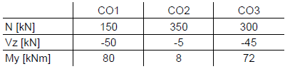
The results of three load combinations are calculated in the second example. These cannot be combined, of course, but it is possible to compare the alternatively acting ones to each other. The goal is to get the maximum and minimum forces in a similar way as in the first example. The following values are available:
The result combination is defined as follows:
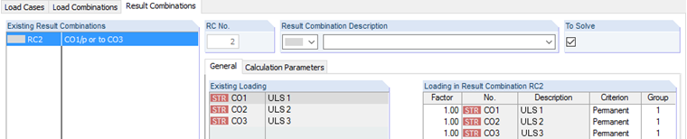
The results of the load combinations already include almost all partial safety factors and combination coefficients. Thus, the factor remains 1.0. To perform the alternative analysis, each load combination must have the same group number. This way, the result of CO1, CO2, or CO3 is recorded. It is also important to assign the "Permanent" criterion to all combinations. That is, the result of three combinations must always be used. If the "Permanent" criterion is assigned to all combinations, the minimum normal force would not be 150 kN, but 0 kN. In this case, the normal force is zero if none of the three load combinations is acting. The maximum and minimum internal forces are displayed in the following table:
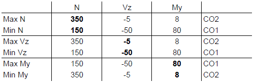
For clarification, the first line will be explained again. We are looking for the maximum normal force. These can be found in CO2 as 350 kN. To obtain Vz and My, it is only necessary to adopt the corresponding internal forces from CO2. Thus, the resulting Vz is −5 kN and My is 8 kNm. These results can be used further for design in add‑on modules.
Conclusion
This article describes the basis of defining result combinations and explains the most common applications in an example. Of course, it is also possible to combine these definition procedures. This will be explained together with a comparison of load combinations in Part 2 of this article series.