


The design rules according to EC5 [1] are explained for the timber panel wall already presented in the article Design of Timber Panel Wall with Beam Panel Thickness Type. Material and geometry properties are based on this article; they are not determined here again.
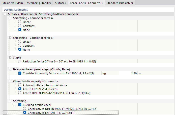
To design the fasteners (brackets 1.5 x 50), additional settings are made in the "Beam Panel | Connectors" tab:
- Forces are not smoothed
- No reduction smaller than 30° ([1], 8.4(5))
- Increase factor ksr=1.2 ([1] , 9.2.4.2(5))
- Load-bearing capacity of the bracing according to Johansen ([1] , 8.2.2(1))
- Buckling design simplified according to ([1] , 9.2.4.2(11))
The timber panel wall has sheathing on one side.
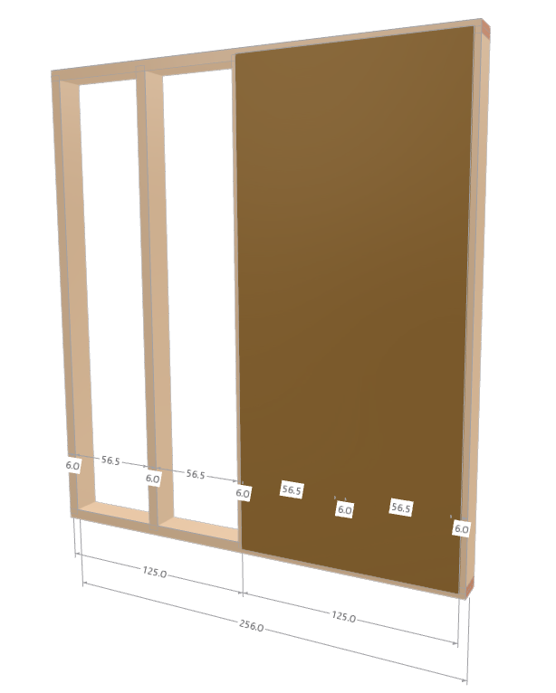
The plate width is applied with a length of 1.25 m. This takes into account the vertical joints in the sheathing. This is a difference from the continuous sheathing in the previous post.

The joints in the sheeting are adjusted to the boundary member centerlines. With a length of 2.56 m, this results in two OSB boards, each with a width of 1.25 m. There is a 3 cm gap on the left and right sides of the board. The geometry is displayed in the following image.
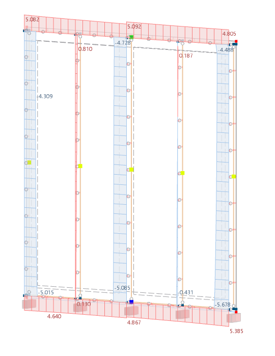
The vertical loads are introduced by the 3D model at the upper frame. The axial force of 6.75 kN/m × 0.625 m = 4.22 kN, which was calculated manually, does not result due to the continuous beam effect.

For illustration purposes, the continuous beam system is compared with a single-span beam system of the upper frame. For Load Combination 2 (1.35*LC1), the maximum axial force of -4.72 kN results from a purely vertical load of 6.75 kN/m. The image shows axial forces with and without the continuity effects.
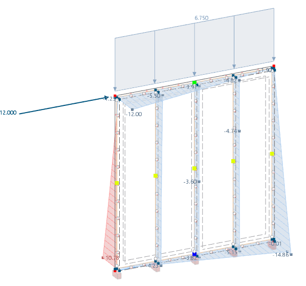
Compared to the previous technical article, an additional line support is defined here, which fails under tension. This makes the modeling more close to reality.
Together with the horizontal force, Load Combination 1 (1.35*LC1+1.5*LC2) results in a compressive force of -14 kN on the back support.

Ribs are considered as laterally restrained against rotation and buckling. Buckling design is performed around the major axis according to [1], 6.3.2.
Design of Supports
.png?mw=760&hash=88e064deab50908aa4bdbff4f8a05080fa460dfb)
Inclinations (imperfections) and wind loads will be discussed in a future article on spatial calculation.
In the sheathing design, there are three failure modes to be analyzed.
- Design of fasteners (shear connection)
- Shear resistance of the OSB/3 board
- Buckling of the sheathing
Based on the clear representation, the information from DIN 1052 [2] is listed in the following two equations. These equations can be found there under numbers 123 and 124.
Design of Fasteners
Charcteristic yield moment ([1], 8.29)
The tensile strength is assumed to be fu,k = 900 N/mm².
Hole bearing strength of the OSB board ([1], 8.22)
Hole bearing strength of timber ([1], 8.15)
Hole bearing strength ratio ([1], 8.8)
Buckling resistance ([1], Equations 8.6 (a-f))

The load-bearing capacity of the brackets is displayed in the program printout. The minimum value has to be used. In this case, Fv,RK,min = 270.4 N
As in the previous post, a bracket consists of two pins, which is why the value can be doubled here. The resulting design value is:
Related to the length with a fastener spacing of 50 mm.
The load is determined from the force n and vz. The forces are displayed in the following image. Centerline 15 of the model obtains the governing forces.

Resulting shear force per connector.
Based on the image, it is clearly visible that, due to the stiffness in the transverse direction, very short but extreme transverse forces vz arise.
To get around this problem, in the beam panel settings, "Connector stiffness in longitudinal direction only" is considered.
.png?mw=760&hash=e8d623815d431fcb7b5d9e193c1e63dda4b2d9a1)
This results in only longitudinal shear forces in the connector, which are displayed in the following image.
The axial force in the support changes to 14.86 kN. It is necessary to perform the buckling design again. Based on the low load, this is not necessary.
The inner line 15 at the point of contact between the two sheathing continues to be governing. The calculation of the resultant forces is not necessary, as there are no longer any transverse forces.
Design 1 – Fastener
A manual comparative calculation of the shear flow results in similar values.
This value is calculated the same way in the result diagrams using the correct smoothing.

Shear Resistance of Plate According to [1], 9.21
- * Single-sided sheathing kda = 0.33 or 1 ([1], Equation NA.16)
- fv,d = 5,23 N/mm²
- t = 15 mm
If the “Consider connector stiffness in longitudinal direction only” option selected in Design 1 is not selected, the value for kda is equal to 1.0.
The design then looks as follows.
If only the longitudinal stiffness is taken into account, the coefficient for single-sided sheathing is 0.33 and is listed below.
The back term of the equation becomes zero, because the stiffness of the bracing is only applied in the longitudinal direction.
Shear Buckling of Plate According to [1], 9.2.4.2
- bnet = 565 mm (clear distance of ribs)
- bnet = 565 mm/15 mm = 37.7 less than 100
→ The simplified buckling design is fulfilled.
Since the value is greater than 35, a more precise design is carried out according to German NA.
- Shear strength OSB fv,k = 6.8 N/mm²
- Partial safety factor yM = 1.2
- Modification factor kmod = 1.0
- Factor according to NCI 9.2.4.2 kda = 0.33 or 1
- Distance of ribs br = 62.5 cm
If the “Consider connector stiffness in longitudinal direction only” option selected in Design 1 is not selected, the value for kda is equal to 1.0.
The design then looks as follows.
If only the longitudinal stiffness is taken into account, the coefficient for single-sided sheathing is 0.33 and is listed below.
Based on the fact that only the longitudinal stiffness is taken into account, the rear term is also omitted in this design.
