


System
- Beam material = C24
- ϱm,s (C24) = 420 kg/m³
- Beam cross-section = 6/16 cm
- Sheathing material = OSB 3
- ϱk,p (OSB) = 550 kg/m³
- t = 15 mm with one-side sheathing
- Staples d=1.5 mm, t=50 mm
- Staple spacing av = 75 mm (single row)
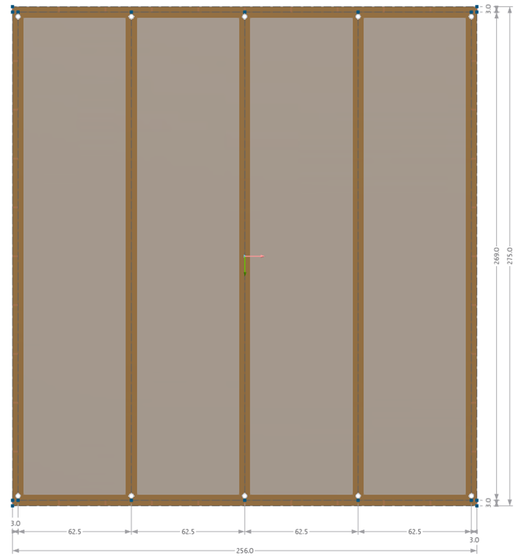
- Grid = 62.5 cm
- Wall length = 2.56 m
- Wall height = 2.75 m
- Load 8 kN horizontal
- Load 5 kN/m vertical
- Service Class 1
Slip Modulus kser
In the beam panel generator, the slip modulus is calculated according to Table 7.1 when performing a calculation according to Eurocode 5. This is explained for fasteners in this article.
According to EN 1995‑1‑1, the square root of the mean value of the density of the sheathing and the columns is used to calculate the slip. If the mean value of the raw density is not available, the characteristic value of the material library is multiplied by the value 1.15 according to ÖNORM EN 1995‑1‑1 (NA.7.1‑E1). This value can be user-defined in the material parameters.

Since the fastener has two nails, the slip modulus is calculated as follows.
In the attached file, this value is also calculated for the beam panel.
The sheathing of the timber panel wall is connected linearly elastic to the timber posts.
Divided into one meter of length, this results in:
1,000 mm / 75 mm = 13.33 connectors
→ 13 connectors x 404.6 N/mm = 5,260 kN/m²
Actually, the unit is kN/m, but the stiffness is defined on a line, and therefore refers to one meter.
--> kN/m x m =kN/m²

The tie rod is not taken into account!
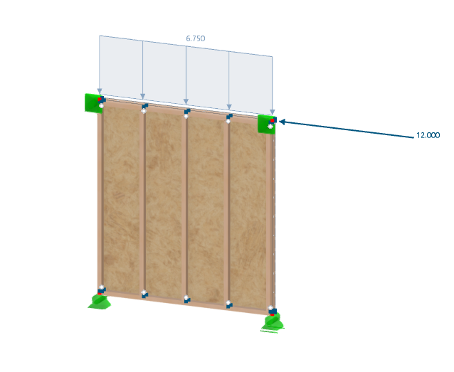
Loading
- LC1 self-weight 5 kN/m (vertical)
- LC2 Wind 8 kN (horizontal)
- CO = 1.35 LC1 + 1.5 LC2
- Calculation according to the linear static analysis
Horizontal deformation behavior of the timber panel wall pure horizontal load (8 kN):
- Fastener in cladding uk,inst
- Shear panel cladding uG,inst
- Ribs (axial force members) uE,inst
The sum of the deformations for the horizontal deflection of 8 kN is 3.2 mm. This corresponds to the calculation in RFEM.
When calculating the load combination (1.35 LC1 + 1.5 LC2), the deflection of 4.8 mm for the force of 12 kN in the manual calculation corresponds well to the calculation in the program of 4.8 mm.
In further design checks, the internal forces and the design should be compared.
