53 Results
View Results:
Sort by:

The design of cold-formed steel members according to the AISI S100-16 is now available in RFEM 6. Design can be accessed by selecting “AISC 360” as the standard in the Steel Design add-on. “AISI S100” is then automatically selected for the cold-formed design (Image 01).

Custom sections are often required in cold-formed steel design. In RFEM 6, the custom section can be created using one of the “Thin-Walled” sections available in the library. For other sections that do not meet any of the 14 available cold-formed shapes, the sections can be created and imported from the standalone program, RSECTION. For general information on AISI steel design in RFEM 6, refer to the Knowledge Base article provided at the end of the page.

The ASCE 7-22 Standard [1], Sect. 12.9.1.6 specifies when P-delta effects should be considered when running a modal response spectrum analysis for seismic design. In the NBC 2020 [2], Sent. 4.1.8.3.8.c gives only a short requirement that sway effects due to the interaction of gravity loads with the deformed structure should be considered. Therefore, there may be situations where second-order effects, also known as P-delta, must be considered when carrying out a seismic analysis.

The classification of cross-sections according to EN 1993‑1‑1 and EN 1993‑1‑5 can be carried out automatically in the RF‑/STEEL EC3 add-on module. The maximum c/t ratios are specified in the standard for straight cross-section parts. There are no normative specifications for curved cross-section parts; therefore, the cross-section classification cannot be performed for these cross-section parts.
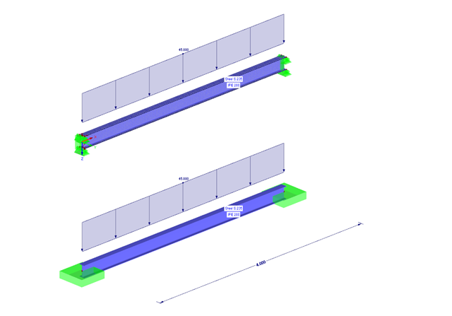
The following example presents a comparison between a shell model and a simple member model performed in RFEM. In the case of the shell model, there is a beam suspended in surfaces, which is modeled with restraints on both sides due to the boundary conditions. This is a statically indeterminate system that forms plastic hinges when overloaded. The comparison is carried out on a member model that has the same boundary conditions as the shell model.

The calculation of complex structures by means of finite element analysis software is generally performed on the entire model. However, the construction of such structures is a process carried out in multiple stages where the final state of the building is achieved by combining the separate structural parts. To avoid errors in the calculation of overall models, the influence of the construction process must be considered. In RFEM 6, this is possible using the Construction Stages Analysis (CSA) add-on.

When connecting tension-loaded components with bolted connections, the cross-section reduction due to the bolt holes must be taken into account in the ultimate limit state design. This article describes how the design of the tension resistance according to DIN EN 1993‑1‑1 can be performed with the net cross-section area of the tension member in the RF‑/STEEL EC3 add-on module.

Imperfections in construction engineering are associated with production-related deviation of structural components from their ideal shape. They are often used in a calculation to determine the equilibrium of forces for structural components on a deformed system.

Both the determination of natural vibrations and the response spectrum analysis are always performed on a linear system. If nonlinearities exist in the system, they are linearized and thus not taken into account. Straight tension members are very often used in practice. This article will show how you can display them approximately correctly in a dynamic analysis.

In the following example, the stability analysis of a steel frame can be performed according to the General Method in compliance with EN 1993‑1‑1, Sect. 6.3.4 in the RF‑/STEEL EC3 add-on module. The first of my three posts shows the determination of the critical load factor for design loads required by the design concept, which reaches the elastic critical buckling load with deformations from the main framework plane.