Example
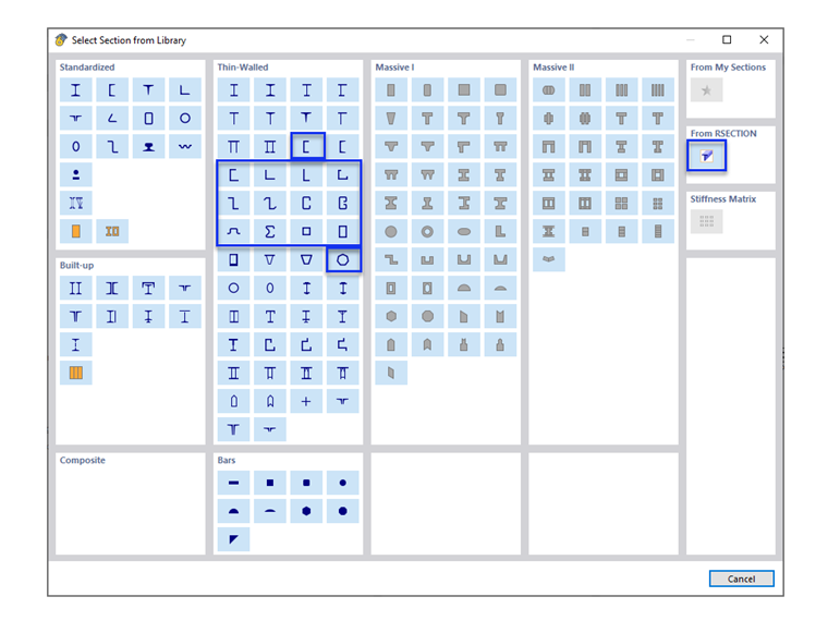
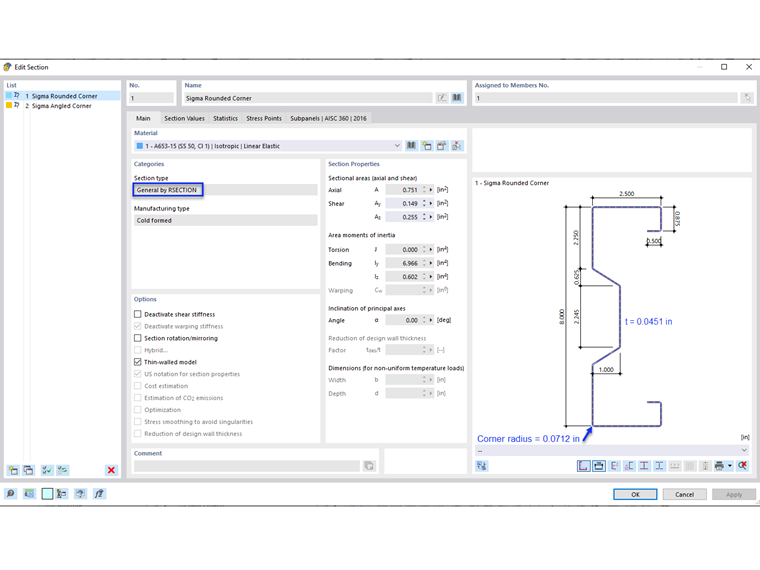
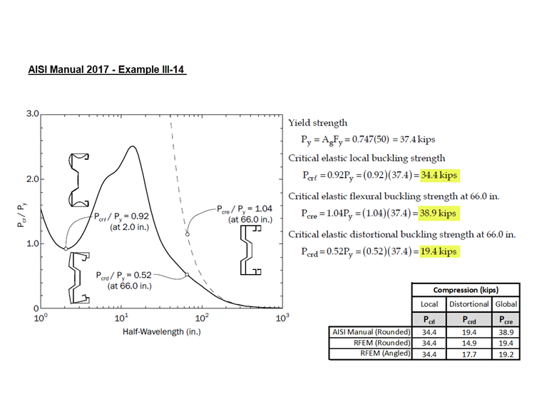
Example III-14 of the AISI manual [1] is used to compare the results obtained from the RFEM model. Since the cross-section does not match any of the Thin-Walled sections, RSECTION is utilized to create the custom sigma section. A webinar showing how to create a custom shape in RSECTION is provided at the bottom of this article.
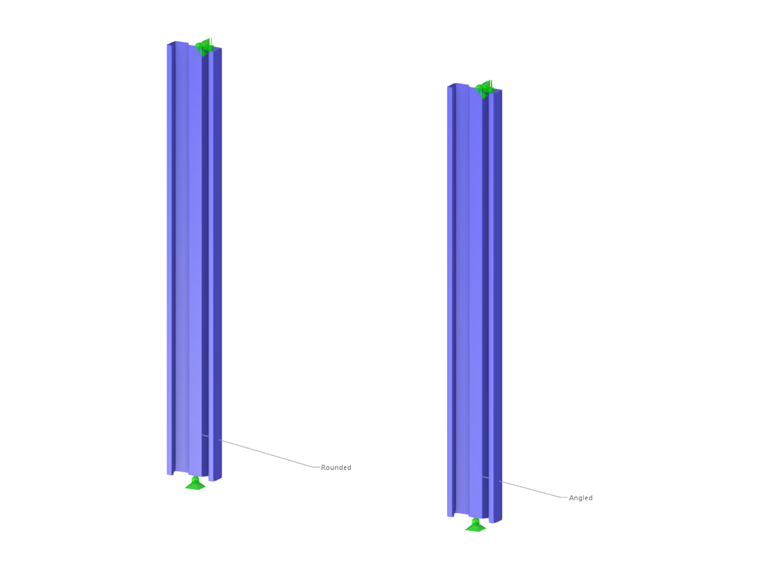
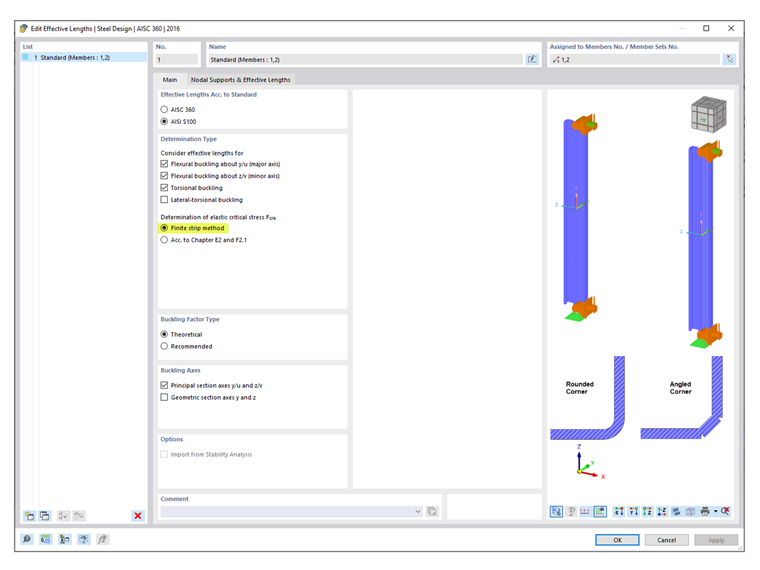
The example presents two cases where the member is fully braced along its length (Case 1) and braced at 66 inches (Case 2). Only Case 2 using the LRFD method is examined in this article. The Finite Strip Method (FSM) is selected to calculate the available compressive strength, Pa. Two (2) 66-inch-long simply supported members are modeled in RFEM using a rounded corner and an angled corner (Image 03). The reason for using a straight-line section (angled corner) is explained subsequently.
Compressive Strength
The critical elastic buckling loads (Pcrl, Pcrd, Pcre) required to determine the available compressive strength, Pa are presented below.
Pcrl (Local)
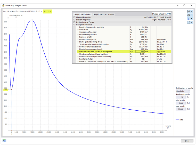
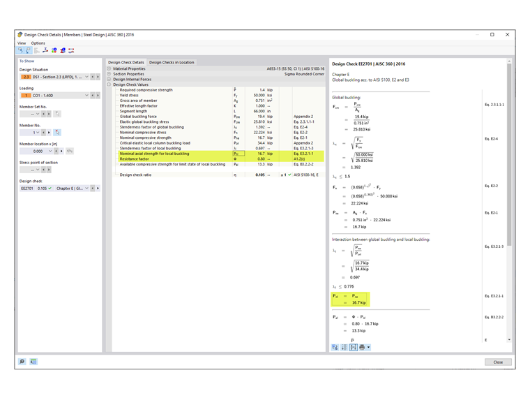
The critical elastic local column buckling load, Pcrl equals 34.4 kips, is shown under the global buckling design check EE2701 and agrees with what is shown in the AISI example. The total curve shows a distinct first minimum where Pcrl equals 33.8 kips is obtained for both the rounded corner and angled corner sections (Image 04). The small discrepancy between the values listed in the design check and the plot is negligible.
Pcrd (Distortional)
The critical elastic distortional column buckling load, Pcrd, is shown under design check EE2801. For the section with rounded corners (rounded section), Pcrd equals 14.9 kips. It can be seen from the signature (total) curve that the second minimum is not distinct. In such a case, the distortional curve is used to identify the appropriate length along the horizontal axis. From there, the location is projected to the total curve to obtain the critical load factor.
The individual curves (local, distortional, global) can be displayed separately from the drop-down menu (Image 05). For custom sections, it could take some time to load the individual graph.
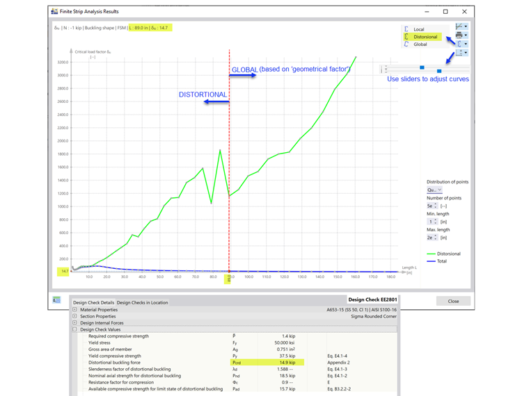
The 14.9 kips at 89-inch length is the last relevant minimum on the distortional graph. Buckling shapes beyond this length are categorized as global buckling. RFEM applies a “geometrical factor” to characterize the buckling shapes as global or distortional.
The AISI manual states, “Examination of the mode shape for the member at a length of 66 inches shows both lateral translations associated with flexural (global) buckling and distortional buckling; consequently, the elastic buckling load at this length is used for the distortional buckling limit state check” [1]. At a 66-inch length, Pcrd equals 19.4 kips on the total curve.
Due to the difference in the approach, the RFEM value of 14.9 kips at the 89-inch length is lower than the 19.4 kips at the 66-inch length listed in the AISI example.
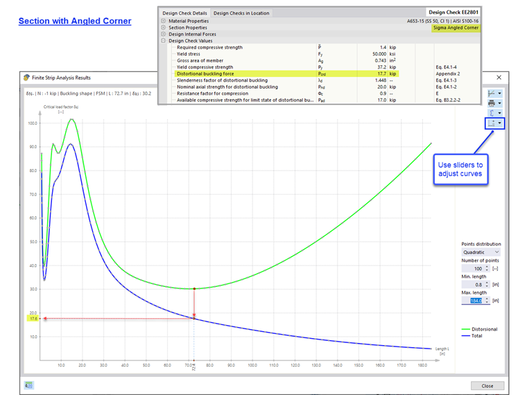
Straight-Line Section (Angled Corner)
When using a rounded section (rounded corner), the FSM solver divides the rounded corners into many small segments. In doing so, the calculation can be conservative. An option to verify the result is to model the section using straight lines (angled corners). For the straight-line section, Pcrd equals 17.7 kips. This value is closer to the 19.4 kips listed in the AISI example (Image 06).
Pcre (Global)
The elastic global (flexural, torsional, flexural-torsional) buckling load, Pcre, is shown under design check EE2701.
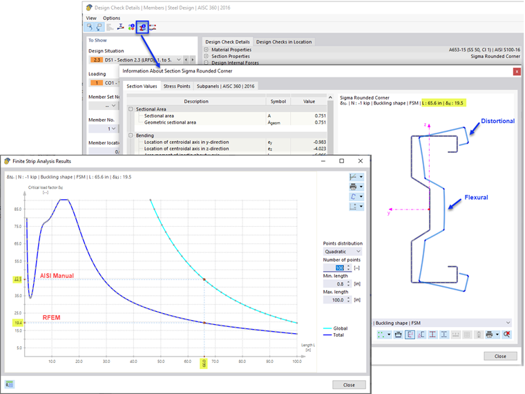
Pcre equals 19.4 kips for the rounded section and 19.2 kips for the straight-line section. These values are taken from the total curve at the 66-inch length. As can be seen in Image 07, the buckling shape at this length contains both flexural (global) buckling and distortional buckling.
The AISI manual states, “The dashed line superimposed on the right half of the graph represents the global buckling mode isolated from other limit states. The elastic buckling load at this length from this line is used for the global buckling limit state check” [1]. Consequently, the Pcre equals 38.9 kips listed in the AISI example is taken from the individual global curve (Image 08).
RFEM takes the conservative approach of obtaining Pcre from the total curve instead of the global curve. Engineers can use their own judgement to use the higher value shown on the global curve after examining the buckling shapes at the 66-inch length. In RFEM, the alternative Pcre value equals 44.3 kips on the global curve (in the proximity of the 38.9 kips value listed in the AISI example).
Nominal Compressive Strength
The nominal compressive strength is taken as the smallest of the values according to the following AISI sections [2]:
- Section E2 – Yielding and Global Buckling
- Section E3 – Local Buckling Interacting with Yielding and Global Buckling
- Section E4 – Distortional Buckling
In RFEM, Section E3 is the governing case with Pnl equals 16.7 kips (Image 09). In AISI manual, distortional buckling (Section E4) is the governing case with Pnl equals 21.0 kips.
AISI Table B4.1-1 Applicability Limits
The safety factor, Ω or resistance factor, Φ used in Chapters E through H are only appropriate for sections that comply with the limitations in Table B4.1-1. For all other sections that exceed any of the limits, higher safety factors or lower resistance factors are applied according to Section A1.2(C). In RFEM, this limitation is checked by default. The user has the option to deactivate this check in the Strength Configuration (Image 10).
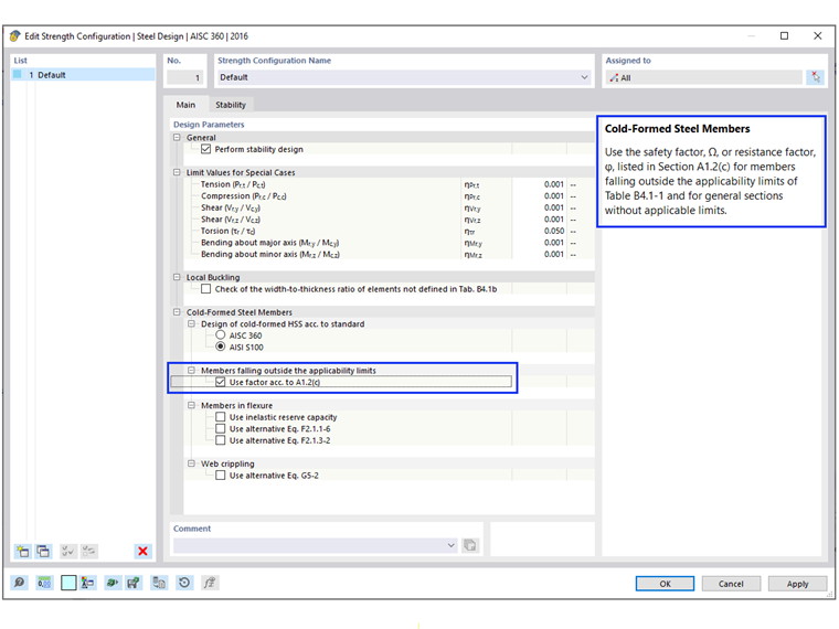
Shapes that can be checked in RFEM include C, Z, L, I (double back-to-back C), hat, rectangular and round HSS. For all other general/complex sections such as the sigma section used in this example, the more conservative factors are automatically applied. As a result, Φc equals 0.80 is shown in RFEM design checks (Image 09).
Calculation in the AISI manual [1] shows that the sigma section actually meets the applicability limits and Φc equals 0.85 can be used.
Stiffened elements in compression:
w/t = [8.00 - 2(0.0451 + 0.0712)] / 0.0451 = 172 ≤ 500 OK
Edge-stiffened element in compression:
b/t = [0.875 - 2(0.0451 + 0.0712)] / 0.0451 = 14.2 ≤ 160 OK
Unstiffened element in compression:
d/t = [0.500 - (0.0451 + 0.0712)] / 0.0451 = 8.51 ≤ 60 OK
Inside bend radius:
R/t = 0.0712/ 0.0451 = 1.58 ≤ 20 OK
Single edge stiffener length/width ratio:
do/bo = 0.500 / 0.875 = 0.571 ≤ 0.7 OK
Edge stiffener type: Simple or complex OK
Maximum number of intermediate stiffeners in w: nf = 1 ≤ 4 OK
Nominal yield stress: Fy = 50 ksi ≤ 95 ksi OK
Conclusion
Custom cross-sections can be created in RSECTION and imported into RFEM 6 for design according to AISI S100 or CSA S136. When analyzing a complex section, it is important to examine the buckling shapes and the signature (total) curve to determine if additional evaluation (that is, using a straight-line section) should be performed. A straight-line section without rounded corners can at times provide a better signature curve and result.
In a case where the mode shows both flexural (global) buckling and distortional buckling, RFEM applies a “geometrical factor” to characterize the buckling shape as global or distortional buckling.
By default, RFEM checks the applicability limits of Table B4.1-1 and applies the more conservative factors for general/complex sections without applicable limits.