10 Results
View Results:
Sort by:

RFEM and RSTAB programs provide parameterized input as an advantageous product feature to create or adjust models by means of variables. This article will show you how to define global parameters and use them in formulas to determine numerical values.
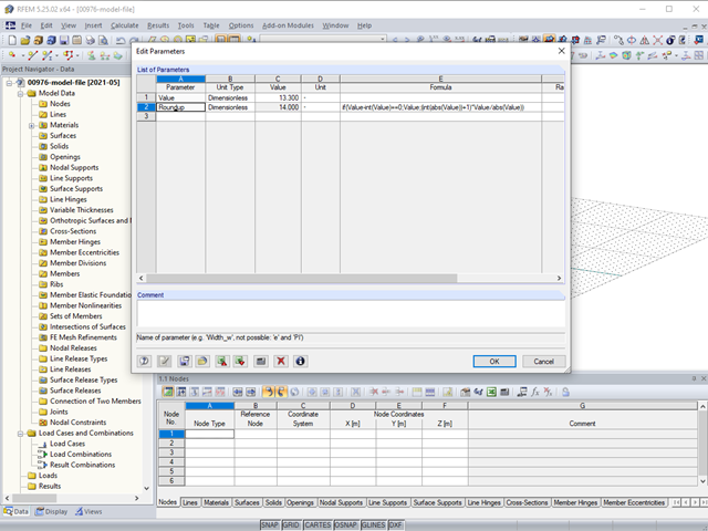
In RFEM, RSTAB, and SHAPE-THIN, you can use formulas to determine a numerical value.
In the Formula Editor environment, you can specify any parameters (lengths, force values, and so on) to control load and geometry data in the modeling.
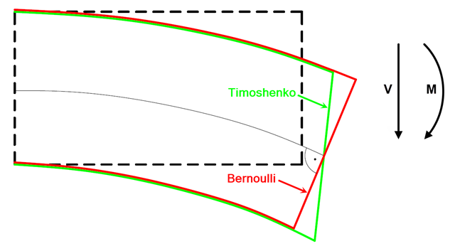
In current literature, the formulas used to determine internal forces and deformations manually are usually specified without considering the shear deformation. The deformations resulting from shear force are often underestimated in timber construction in particular.

When designing bending-resistant connections from I-beams, the connection is dissolved into the individual parts. For these basic components of a joint, there are separate formula calculators for load-bearing capacity and stiffness. In RFEM and RSTAB, frame joints can be designed using the RF-/FRAME-JOINT Pro add-on module.
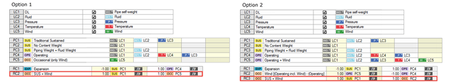
The RF-PIPING and RF-PIPING Design add-on modules allow you to design piping systems according to EN 13480-3 [1], ASME B31.1 and B31.3. In the case of the European standard, the determination of pipe stresses is based on the formulas of Section 12.3 Flexibility Analysis. Depending on the stress type, one or more resulting moments is applied without regard to each other. This differentiation occurs when determining the stresses due to occasional loads, for example.
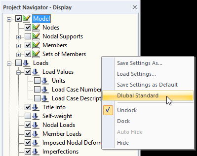
When you receive an RFEM or RSTAB file for further processing, the structures will be displayed in the program using the display settings of the last editor. If the settings do not correspond to your requirements, you can simply right‑click the empty area in Project Navigator - Display and select "Dlubal Standard". This returns the settings to the default values.
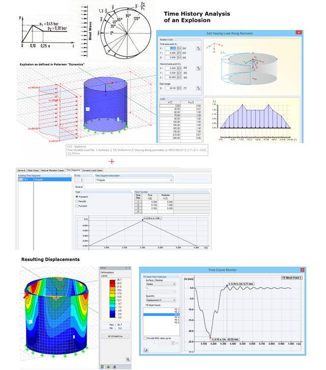
With RF-DYNAM Pro – Forced Vibrations, you can perform a time history analysis. For example, you can analyze an explosion acting on a nearby building structure. In "Dynamik der Baukonstruktionen" by Christian Petersen, formulas for time diagrams and load distribution are described to specify an explosion. The image shows the input of such an explosion load. Free variable loads are available in RFEM that enable flexible load distributions.
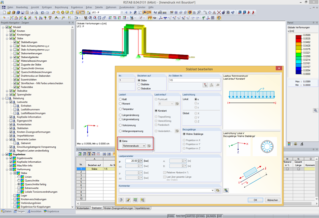
In addition to bending, torsional, longitudinal, and strain loads, you can define and analyze the internal pressure of members with circular hollow cross‑sections in RFEM and RSTAB. The following perimeter and axial stresses resulting from the internal pressure load are analyzed using Barlow's formula and transferred to design modules in order to superimpose the remaining stresses due to internal forces.
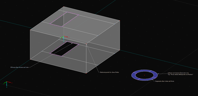
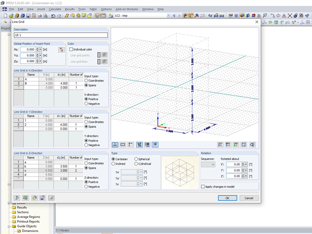
For recurring elements such as certain structural components or standard parts, you can use the parametrization of a basic model. In the program, the main elements do not represent components but the corresponding node and therefore, they have to be parameterized. For example, a member is not defined by the length, but by the start and end nodes. In this way of modeling, complex formulas may occur especially in the case of three-dimensional structures.