


This article will show you how to parameterize the bracing element of the truss cell shown in the model.
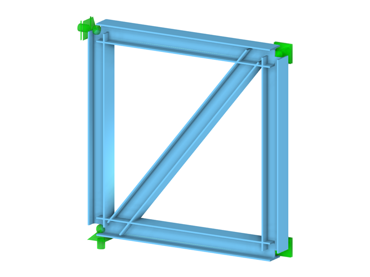
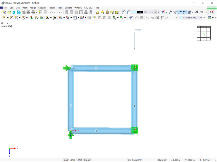
Assuming that the structure has already been modeled in RFEM 6 by assigning members and defining boundary conditions as shown in Image 1, the next step is to define the bracing. As mentioned previously, this element will be defined using a parameterized input. This way, the parameters can be optimized later, and the program can automatically determine the optimal position of the element.
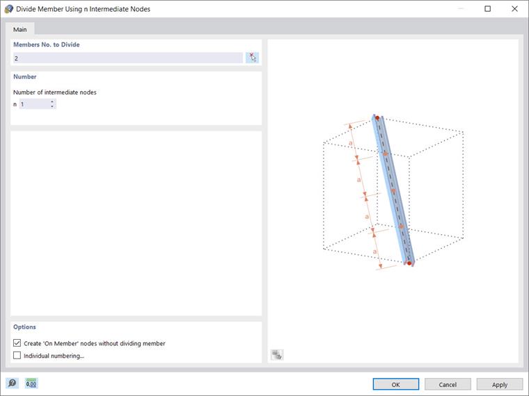
First, you can create intermediate nodes on both the top (Member 2) and bottom (Member 3) chords and connect them with a simple line. To define these nodes, right-click on individual member → divide member → n intermediate nodes. It is important to create the nodes without literally dividing the members; therefore, you should select the associated check box as shown in Image 2.
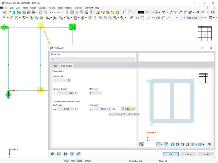
By doing so, you can see in the nodes’ properties that they have the type “On Member”, and the member remains a whole element. Since the individual member has been divided by one intermediate node, the relative distance between the created node and the start and end nodes of the member is 50%. However, the four input fields are interactive, and in addition to this relative specification, you can enter the value as an absolute distance (that is, length).
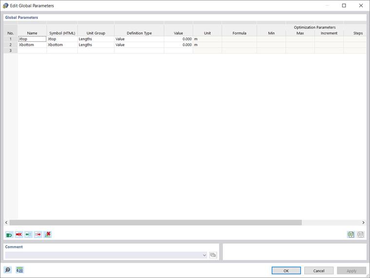
Now you can start assigning the parameters via the Edit menu → Global parameters. The variables to be defined are from the “length” unit group, since we are interested in positioning the bracing element that is represented by the position of its nodes on the upper and lower chords.
Hence, you can define the parameters as shown in Image 4; one for the upper (Xtop), and another for the lower chord (Xbottom). This way, the position of the nodes will be defined with respect to the specific values assigned to these parameters.
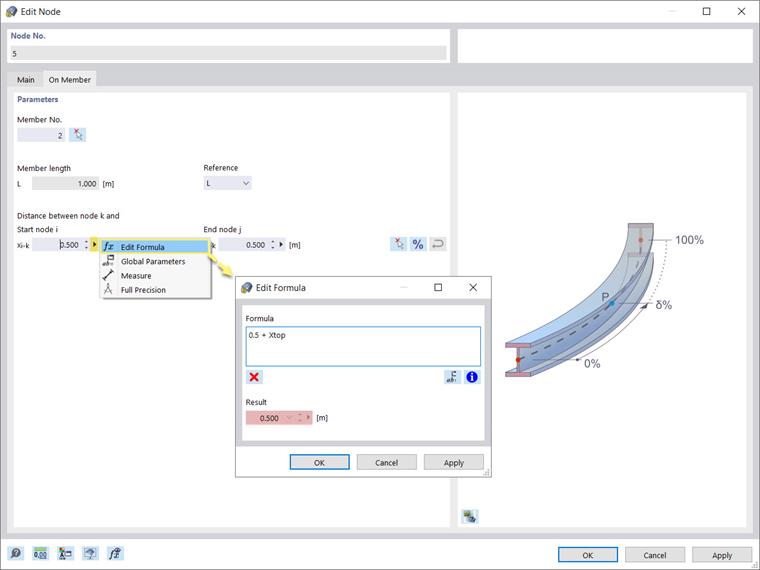
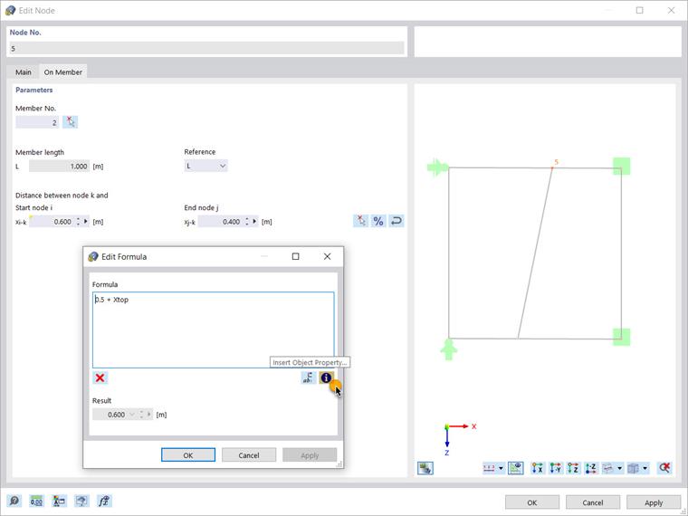
Once the parameters have been defined, you can use them in formulas to determine the numeric values. This can be done in the “Edit” window of the individual nodes, where you can use the formula editor to write a formula for determining the distance of the node to the start node of the member.
For instance, the equation shown in Image 5 indicates that this length will be calculated as the value of the parameter Xtop added to 0.5 m. Given that Xtop was initially set to 0, the equation results in 0.5, meaning that the node will stay at a distance of 0.5 m (Image 6).
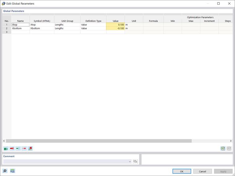
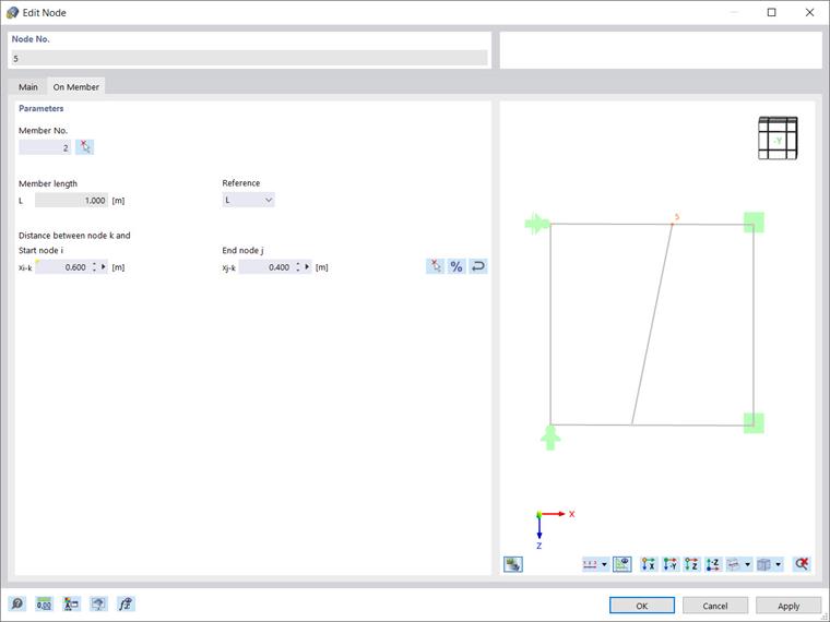
The advantage of the parameterized input is that if a parameter is changed in the parameters list, the results of all formulas using this parameter are modified. Thus, if you reopen the Global Parameters list and set the value of Xtop as 0.1, the distance of the node with respect to the start node of the member will automatically change to 0.6 (Xtop + 0.5) and the node will be moved as shown in Image 7.
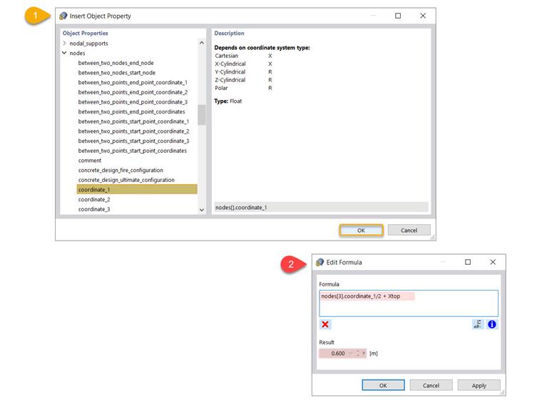
You can go a step further and utilize other advantages of the formula editor, such as inserting an object property in the equation, as shown in Image 8.
Use the associated icon to open the large list of object properties and their subcategories, and select the one you are interested in. For instance, you can select coordinate_1, which is the Cartesian X coordinate of a node. You can indicate the associated node in the formula text box, as shown in Image 9.
In this example, we are interested in calculating the distance of Node 5 with respect to the X coordinate of Node 3. This means that if Node 3 is displaced and its X coordinate is changed, the position of Node 5 will be automatically modified, since this object property is included in the formula.
This article has shown you how to define global parameters and use them in formulas to determine numeric values. These parameters can also be optimized according to different aspects, which will be the topic of a future Knowledge Base article.
