21 Results
View Results:
Sort by:

In this article, the adequacy of a 2x4 dimension lumber subject to combined biaxial bending and axial compression is verified using the RF-/TIMBER AWC add-on module. The beam-column properties and loading are based on example E1.8 of AWC Structural Wood Design Examples 2015/2018.

For designing glass in the RF‑GLASS add‑on module, you can use one of two calculation methods: a 2D or a 3D calculation. The main difference between these design options is the automatic modeling of the layers in a temporary model. In a 2D calculation, each layer is generated as a surface element (plate theory); in a 3D calculation, it is generated as a solid. Depending on the selected layer composition, you can either select an option or find it preselected by the program.

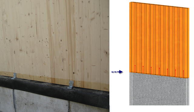
In the case of wall-like load-bearing behavior of the cross-laminated timber plate, special attention must be paid to the shear deformation in the plane of the pane and thus, in particular, to the displaceability of the fasteners.

The support of the cross-laminated timber panel deserves special attention. Usually, a cross‑laminated wall is secured against shearing by means of shear connectors and against lifting forces by means of tie rods.
One of the advantages of entering the structure in RFEM is the complete freedom when selecting the geometry. You can easily select a structure where re‑entrant rolling corners are given as shown in the image.
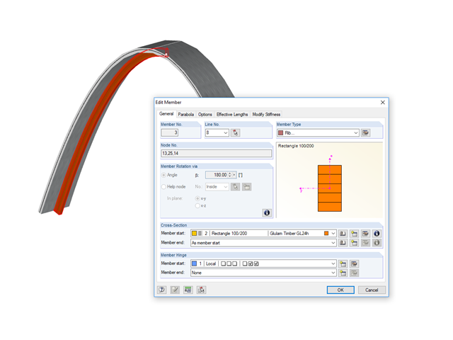
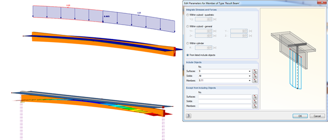
This time, we will look at modeling downstand beams using ribs.

For cross‑laminated structures with large spans, downstand beams or hybrid structures are often used. They can be modeled in RFEM 5 by using surfaces and member cross‑sections. In both structural systems, curved downstand beams are also possible without any problems. In the case of the curved surface, the member is always appropriately generated by means of the automatic member eccentricity with the thickness distance of the surface and the member. The downstand beam can also be connected flexibly by means of a line release.
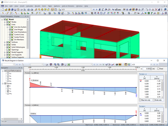
In this article, we will look at the design of shear connectors of cross‑laminated timber structures that transfer the longitudinal forces of the shear wall to the soil.
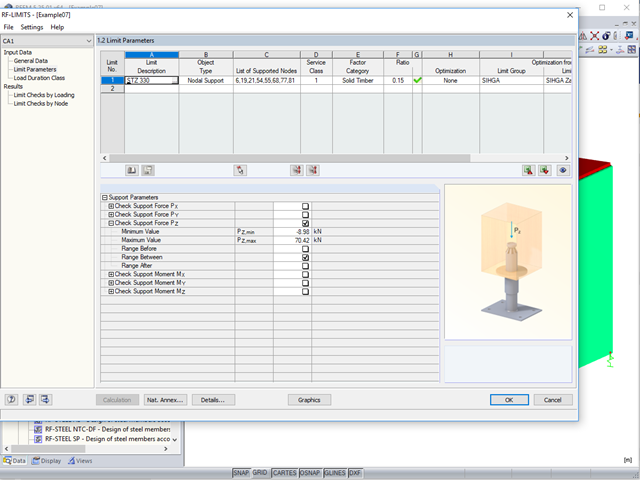
Usually, the lifting forces acting on a structure, which mostly result from wind loads or a dynamic analysis, are transferred into the ground through ties.
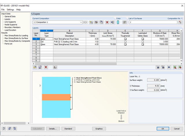
Different glass types and layer structures are available for glass structures used for different purposes. The following types are usually used: float glass, partly tempered glass, and toughened safety glass.
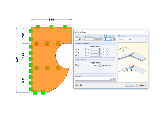
This article deals with considering end releases between surfaces with line hinges and line releases. End releases between surfaces are taken into account using line releases as well as line hinges. The examples are joints in reinforced concrete structures and frame joints in cross-laminated timber structures.
.png?mw=640&hash=44d3f64925841d58547bef5a5e8ff90fab8aceaf)
The American Wood Council (AWC) has released the 2018 Edition of the National Design Specification (NDS) for Wood Construction. This is the second edition of the NDS to contain a chapter dedicated to cross-laminated timber (CLT) design. Therefore, a couple of revisions were included in the 2018 NDS when compared to the previous 2015 Edition.

As an alternative to the equivalent member method, this article describes the possibility to determine the internal forces of a wall at risk of buckling according to the second-order analysis, taking imperfections into account, and to subsequently perform the cross-section design for bending and compression.

The following article describes a design using the equivalent member method according to [1] Section 6.3.2, performed on an example of a cross-laminated timber wall susceptible to buckling described in Part 1 of this article series. The buckling analysis will be performed as a compressive stress analysis with reduced compressive strength. For this, the instability factor kc is determined, which depends primarily on the component slenderness and the support type.

Basically, you can design the structural components made of cross-laminated timber in the RF-LAMINATE add-on module. Since the design is a pure elastic stress analysis, it is necessary to additionally consider the stability issues (flexural buckling and lateral-torsional buckling).
![Forked Beam with Distributed Load (Source: [3])](/en/webimage/009690/467522/01-de-png.png?mw=640&hash=52805a227240ecddbd69b1d113348bf2749c3f9e)
Long-span glued-laminated beams are usually supported by a reinforced concrete column with torsional restraints.
![Vibration Analysis (Source: [3])](/en/webimage/009798/467822/01-de-png.png?mw=640&hash=52805a227240ecddbd69b1d113348bf2749c3f9e)
The vibration design of cross‑laminated timber plates often governs for wide-span ceilings. The advantage of timber as a lighter material compared to concrete is turned into a disadvantage here, since a high mass is advantageous for a low natural frequency.
The last part of my post deals with the consideration of forces resulting from the imposed deformation of a cross‑laminated timber plate when designing a structure with imposed loads.
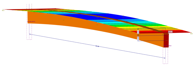
This part explains the determination of forces arising when screwing a straight cross-laminated timber plate to a curved glulam beam. For this, a glulam beam with a curved member was modeled in RFEM. The member has a precamber of 12 cm, since the preliminary design showed that the applied precamber of 6 cm will never be sufficient to maintain l/300. The dimensions of the bottom chord are 12 cm wide by 32 cm high. The plate was selected in RF‑LAMINATE as a three‑layer plate with a thickness of 8 cm.
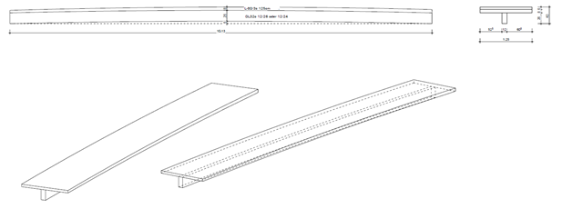
Our client had the exciting task of modeling a cross‑laminated timber plate with a precamber such that, in the case of a span of more than ten meters, the deformation was below the limit value of l/300 = 3.3 cm. The idea was to screw the plate on a glulam beam and then put it together with a glue approved by the building authorities in order to create a rigid bond between the plate and the member.
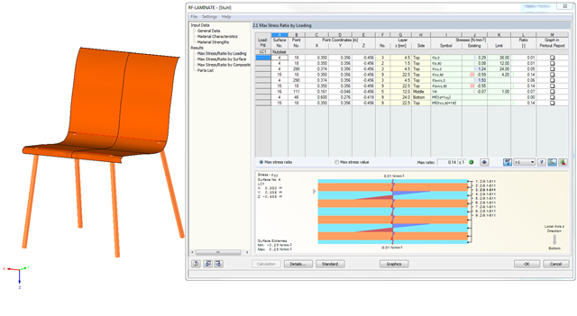
In RF‑LAMINATE, you can also design curved quadrangle surfaces. In the example in the figure, the cross-laminated timber layers of a chair are designed.