


![Forked Beam with Distributed Load (Source: [3])](/en/webimage/009690/467522/01-de-png.png)
On these supports, torsion moments occur that have to be designed according to [2], Section 6.1.9:
The superposition of internal forces from shear force and torsion should prevent cracks on the rigid support.
![Cracks on Glulam Beams (Source: [4])](/en/webimage/009691/467524/02-de-png.png)
The torsional moment on the end supports is caused by beam deflection in the case of a sine‑shaped load (cf. Image 03).
According to [1], the value of l/400 is to be set for the precamber. This is based on the minimum requirement of stiffening the secondary supporting system. More information can be found in [3], for example.
However, the current structural member analysis methods cannot detect torsion on supports. In addition, many calculation programs do not allow for consideration of the cross-section warping. Since the calculation is often performed in 2D structural frame analysis programs, the limiting criterion is provided in [2], Section NCI to 9.2.5.3 (Expression 2):
If the slenderness ratio of the beam is below this value, the torsional stress components can be neglected.
Calculation in RX-TIMBER Glued-Laminated Timber
The following example clarifies this relation.
Structure:
Span = 25 m
Material = GL24c
Cross-section = 12 cm / 242 cm (without ridge wedge)
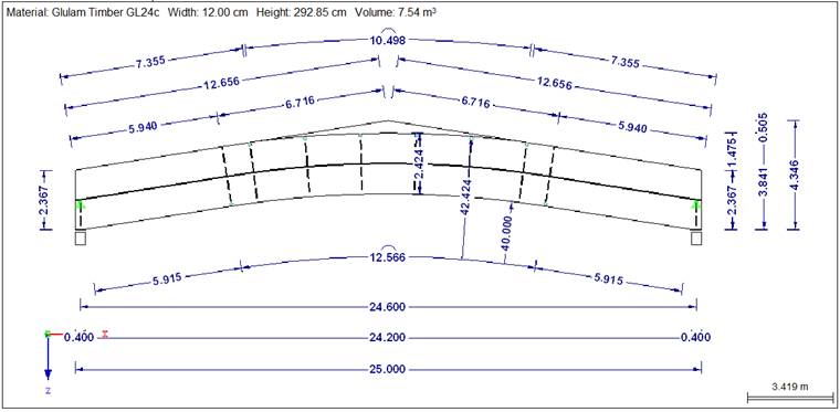
The beam is subjected to a uniformly distributed load of 13.5 kN/m. The self-weight is neglected.
The governing design is the torsional stress analysis specified in Expression 1. In this case, lef is the same as the span length of 2.46 m. Spacing of supports for lateral-torsional buckling can only be applied if the horizontal stiffening of the secondary supporting system is < l/ 500 or l/1,000. This is not applied here.
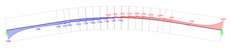
Internal Forces and Stresses:
Calculation Considering Warping Torsion
RF-/FE-LTB allows you to apply the eccentric compression force to the beam. Thus, the uniform load of 13.5 kN/m can be applied eccentrically to the beam.

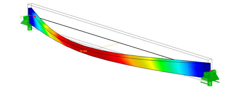
As shown in Image 05, the load eccentricity is set to 6 cm. Furthermore, lateral deformation of 6.15 cm is applied in accordance with [2] (NA.5).
Based on the Bernoulli bending theory, RF‑/FE‑LTB can determine the critical load Fki and thus the ideal elastic critical moment Mki and the torsional buckling load Nki,phi.
The calculation is based on the second‑order torsional buckling theory. The cross‑section warping (7th degree of freedom) is also taken into account.
In order to consider the corresponding roof covering or stiffening due to the secondary supporting system, a rotational spring about the local x-axis of the member is defined. The program converts this spring to the shear center M.

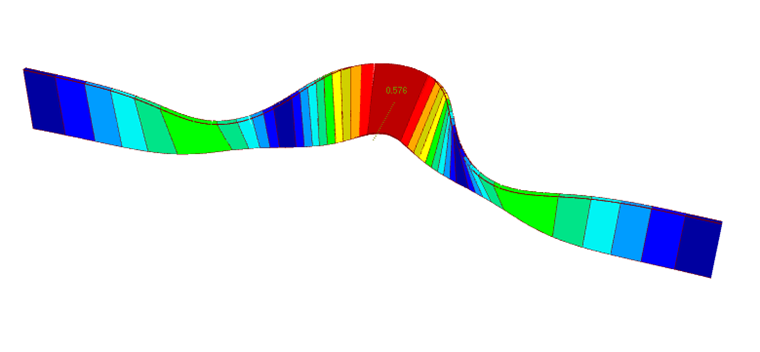
The rotational spring is only applied to obtain the deformation shown in Image 02. A translational spring on the upper flange of the structure would be closer to reality. However, the required imperfection shape cannot be created due to the curvature of the beam. The imperfection shape would then fail in the middle as shown in Image 07. This way, the torsional moments would be reduced significantly.
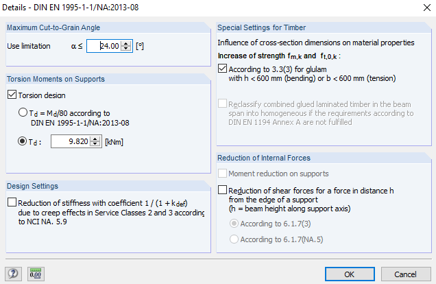
With a rotational restraint of 500 kNm/m, torsional moments of 9.8 kNm result on the supports.
Using this torsional moment, the design of [1] can be performed again in RX-TIMBER Glued-Laminated Beam. For this, the determined torsional moment is defined in RX-TIMBER Glued-Laminated Beam.
Conclusion
The structure can be designed much more economically by considering the warping stiffness of the cross-section.
The difference from the general approach of Section 9.2.5 in [2] is even more serious when replacing a virtual rotational restraint by a translational spring stiffness of 915 N/mm for the longitudinal deformation of a conventional nail in a coupling member, for example.