14 Results
View Results:
Sort by:
,_Table_22.5.5.1_ACI_318-19.png?mw=640&hash=7e50d54e01238943fe1c691c0aa197d9b2fa8511)
With the most recent ACI 318-19 standard, the long-term relationship to determine the concrete shear resistance, Vc, is redefined. With the new method, the member height, the longitudinal reinforcement ratio, and the normal stress now influence the shear strength, Vc. This article describes the shear design updates, and the application is demonstrated with an example.

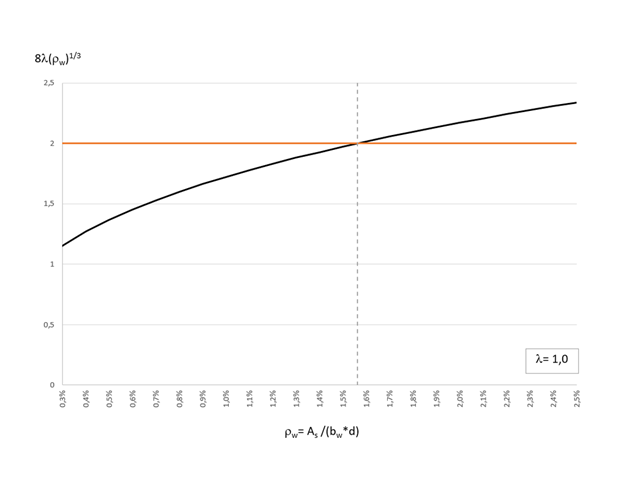
According to EN 1992-1-1 [1], a beam is a member of which the span is no less than 3 times the overall section depth. Otherwise, the structural element should be considered as a deep beam. The behavior of deep beams (that is, beams with a span less than 3 times the section depth) is different from the behavior of normal beams (that is, beams with a span that is 3 times greater than the section depth).
However, designing deep beams is often necessary when analyzing the structural components of reinforced concrete structures, since they are used for window and door lintels, upstand and downstand beams, the connection between split-level slabs, and frame systems.

Steel has poor thermal properties in terms of fire resistance. The thermal expansion for increasing temperature is very high compared to that of other building materials, and might result in effects that were not present in the design at normal temperature due to restraint in the component. As temperature increases, steel ductility increases, whereas its strength decreases. Since steel loses 50% of its strength at temperature of 600 °C, it is important to protect components against fire effects. In the case of protected steel components, the fire resistance duration can be increased due to the improved heating behavior.
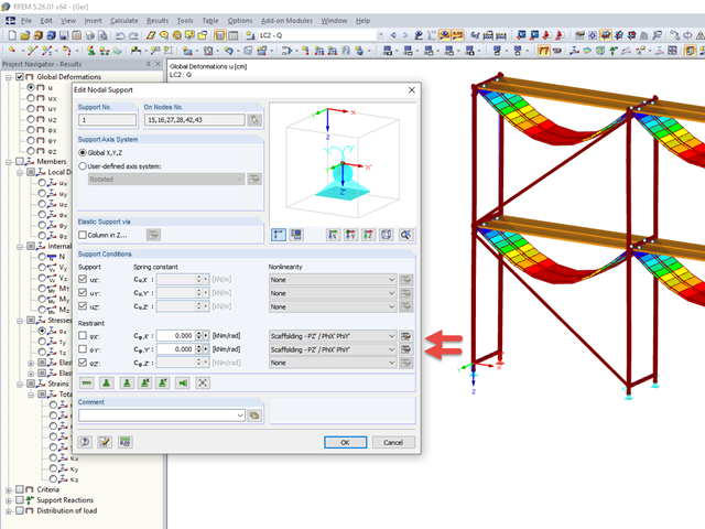
Temporary structures, such as scaffolding or props, are versatile structures that can be adapted very well to different geometric conditions.

In order to detect the governing internal forces of a plate, a checkerboard loading is commonly used. Since it is not necessary to divide the surface into individual load segments, loading is usually carried out by means of free rectangular loads. In the case of many loads, the normal load display can become somewhat confusing.

The classification of cross-sections according to EN 1993‑1‑1 and EN 1993‑1‑5 can be carried out automatically in the RF‑/STEEL EC3 add-on module. The maximum c/t ratios are specified in the standard for straight cross-section parts. There are no normative specifications for curved cross-section parts; therefore, the cross-section classification cannot be performed for these cross-section parts.
The most recent standard ACI 318‑19 redefines the long-term relation for the determination of the concrete shear resistance Vc. With the new method, the member height, the longitudinal reinforcement ratio, and the normal stress now influence the shear strength, Vc. This article describes the shear design updates, and the application is demonstrated using an example.

Fin plate connections are a popular form of pinned steel connection and are commonly used for secondary beams in steel structures. They can be used easily in beam structures arranged on the top edge (for example, working platforms). Manufacturing expenditures in the workshop as well as the onsite assembly costs are normally manageable. The design seems to be completed easily and quickly, but it has to be put into perspective to a certain extent in the following text. Moreover, this connection type is basically possible as a pinned beam-to-beam or pinned beam-to-column connection; the former case is the more common one in design practice.
.png?mw=640&hash=5852c5c8a1cdb9f021a168d75c0a0466fb430ef7)
Lattice towers represent typical applications in steel construction. Examples of this special type of truss structure are antenna and overhead line towers, as well as columns for wind power stations, cable cars, and supporting frame constructions. The modeling can be done individually in RFEM and RSTAB by entering various tower elements. Furthermore, you can use different copy functions and parameterized input options. However, this procedure normally requires considerable effort. It is more convenient to model such structures using prefabricated catalog elements provided by the Block Manager. These elements are automatically stored in the database during program installation. Thus, you can use tower segments, platforms, antenna brackets, cable ducts, and so on as parameterized building blocks for generating diverse tower structures.

Wind is the only climatic load acting on every type of structure in every country in the world, unlike snow. The wind speed depends on the geographic location of the building. Currently, this is one of the main reasons for the necessity of regional division (wind zone) and consideration of the altitude stipulated within the official standards; the variation of the dynamic pressures according to the height above the ground for a "normal" site deprived of masking effect should be taken into account as well.
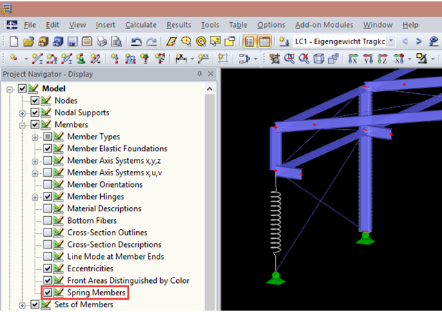
You can display spring members in the Display Navigator. A spring member is displayed as a helix by default. Clear the "Spring Members" check box to display them as normal lines.
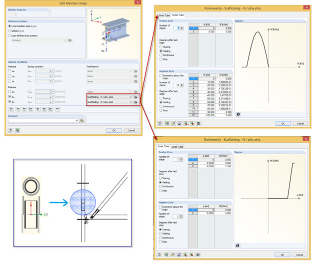
In RFEM, you can simulate a scaffolding tube joint (butt joint with a stub) by a nonlinear member release of the "Scaffolding" type. The joint considers moment resistance dependent on compression forces existing between two outer tubes, and the stub also has certain moment resistance based on its bending resistance.
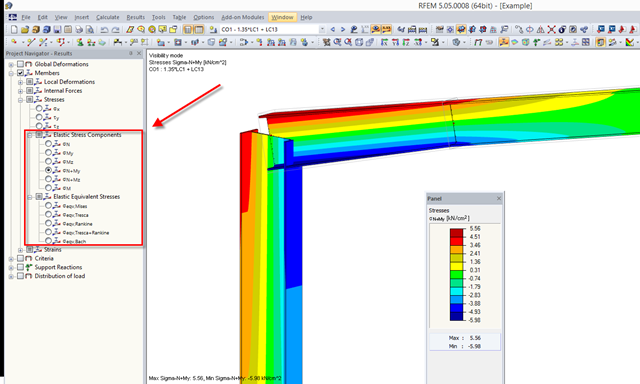
RFEM 5.04.xx allows for graphical visualization of normal and shear stress of members (this feature is available only if the RF‑STEEL add‑on module is licensed).
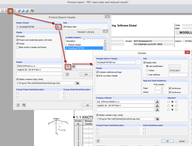
Sometimes, it is necessary to change the printout report header in a 3D PDF. To do this, adjust the header of the normal printout report. The new printout report header is then also applied for the 3D PDF.