Fire Resistance Design in RFEM 6
In RFEM 6, it is possible to define the fire resistance configuration for steel design with the tables shown in Image 1 and by using the accidental design situation for the fire resistance design. The governing action of this design situation is then compared to the design resistance for fire temperature, resulting in the design check ratio, which has to be lower than 1 in order for the design to be fulfilled. The design value of the resistance is obtained by reducing the yield strength due to the increased temperature, whereas the reduction factor depends on the steel temperature θa at the end of the required time of fire resistance and it is interpolated from [1], Table 3.1.
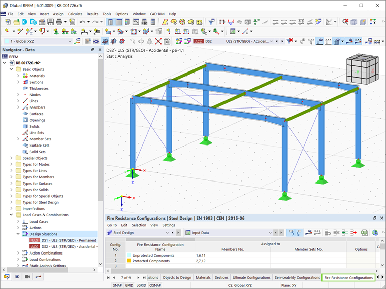
Fire Design Parameters in RFEM 6
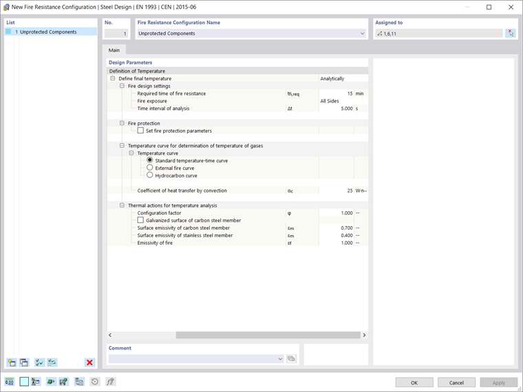
The fire design parameters in RFEM 6 can be adjusted in the window shown in Image 2. If the final temperature is to be defined analytically, the required time of fire resistance and the time interval of analysis have to be defined.
The steel temperature θa at the end of the required time of fire resistance tf,req is obtained by calculating the increase of temperature for the steel Δθa at each time interval of analysis according to Equation (4.25) of [1]. The steel temperature for the next time step is obtained from the sum of the steel temperature of the previous step and the heating Δθa until the point time t, where the governing steel temperature is obtained.
|
ksh |
Correction factor for considering shadowing effect |
|
Am/V |
Section factor (represents the ratio of the exposed surface area to the volume) |
|
ca |
Specific heat capacity |
|
ρa |
Density of steel |
|
Δt |
Interval for the time step |
|
hnet,d |
Net heat flux |
The design parameters that affect the calculation of the final temperature have to be determined in the fire resistance configuration shown in Image 2. Hence, the number of cross-section sides that are exposed to fire has to be defined, since it affects the determination of the section factors according to [1], Tables 4.2 and 4.3.
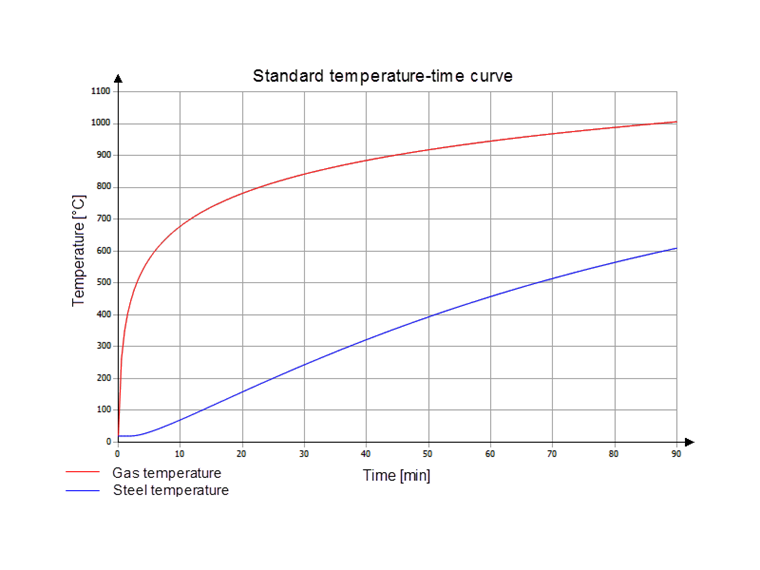
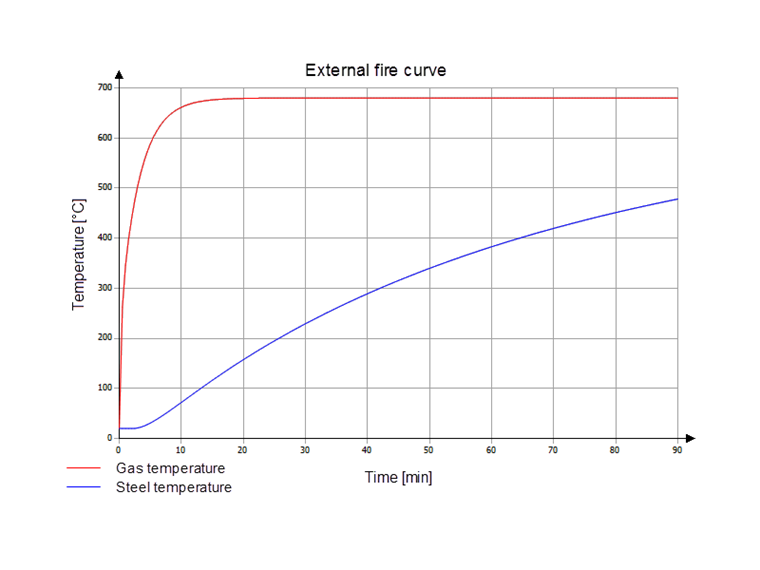
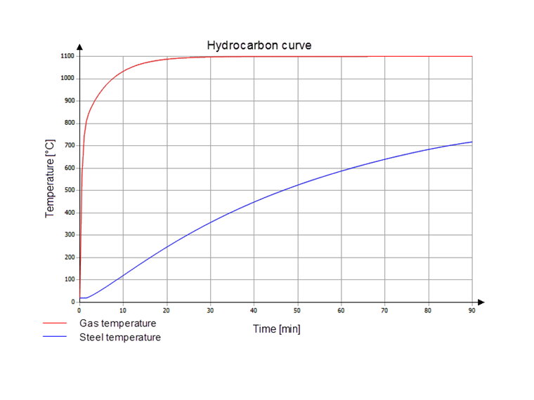
Next, the temperature curve to determine the gas temperature has to be selected. Three curves are available for selection: the standard time-temperature curve (ETK), the external fire curve, and the hydrocarbon fire curve (Image 3 to Image 5). The program can determine the gas temperature based on these diagrams.
The configuration factor, the emissivity of the steel member, and the emissivity of fire as factors for the determination of net flux according to [1] and [2] are preset by the program, but the user can adjust them to specific conditions. The favorable effect of hot-dip galvanization of structural components can also be taken into account when determining the steel temperature by selecting the "Galvanized surface of carbon steel member" option. In general, the lower surface emissivity of the galvanized surface εm,lim is considered up to the limit temperature. At higher temperatures, on the other hand, the surface emissivity of the carbon steel (εm) is taken into account.
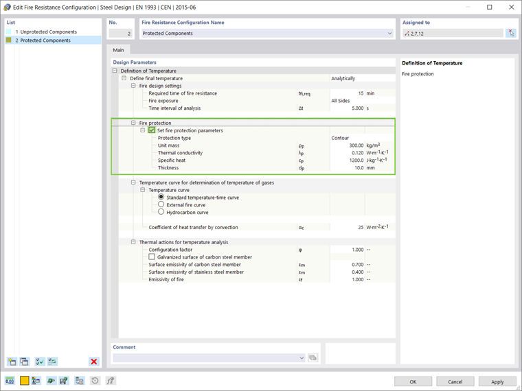
If the steel components are protected against the effects of fire, the user should create a new fire resistance configuration and assign it to these components. The fire protection parameters such as protection type, unit mass, thermal conductivity, specific heat, and thickness of the protection can be defined easily, as shown in Image 6. In this manner, various fire resistance configurations can be defined and assigned to different components. These configurations can differ not only in terms of protection parameters, but also in terms of all the other fire design parameters mentioned above.
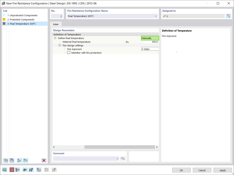
If the user's preference is to define the final temperature manually and not analytically as described in the preceding text, this can be done as shown in Image 7.
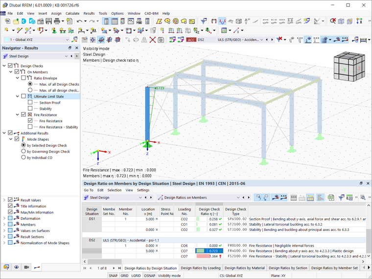
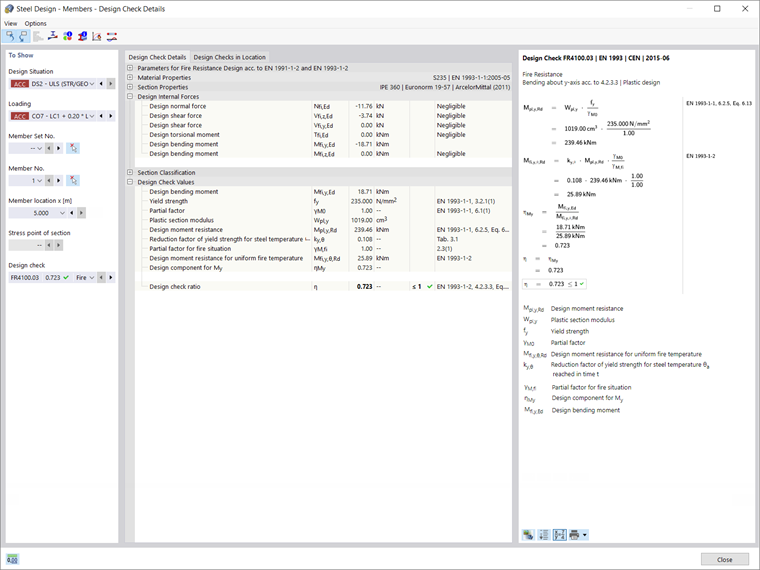
Design Ratios in Terms of Fire Resistance
Once the Steel Design is calculated, the design ratio on members in terms of fire resistance is included in the Results table, as shown in Image 8. The design check details, along with the reference to the equations and tables used for the design check, can also be displayed (Image 9).