
The pushover analysis is managed by a newly introduced analysis type in the load combinations. Here, you have access to the selection of the horizontal load distribution and direction, the selection of a constant load, the selection of the desired response spectrum for the determination of the target displacement, and the pushover analysis settings tailored to the pushover analysis.
In the pushover analysis settings, you can modify the increment of the increasing horizontal load and specify the stopping condition for the analysis. Furthermore, it is possible to easily adjust the precision for the iterative determination of the target displacement.
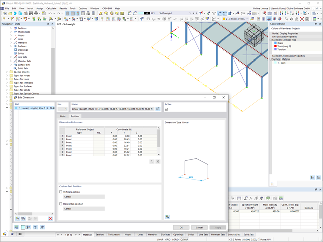
A clear arrangement of the Dlubal programs has a high priority. Therefore, the reference descriptions of incremental dimension lines are now given in tabular form for a better overview.

Compared to the RF‑/STABILITY (RFEM 5) and RSBUCK (RSTAB 8) add-on modules, the following new features have been added to the Structure Stability add-on for RFEM 6 / RSTAB 9:
- Activation as a property of a load case or a load combination
- Automated activation of the stability calculation via combination wizards for several load situations in one step
- Incremental load increase with user-defined termination criteria
- Modification of the mode shape normalization without recalculation
- Result tables with filter option

- Import of relevant information and results from RFEM
- Integrated, editable material and section library
- Sensible and complete presetting of input parameters
- Punching design on columns (all section shapes), wall ends, and wall corners
- Automatic recognition of the punching node position from an RFEM model
- Detection of curves or splines as a boundary of the control perimeter
- Automatic consideration of all slab openings defined in the RFEM model
- Construction and graphical display of the control perimeter
- Optional design with unsmoothed shear stress along the control perimeter that corresponds to the actual shear stress distribution in the FE model
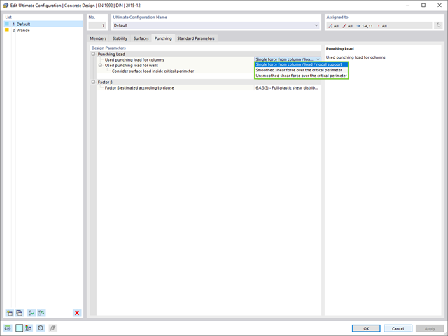
- Determination of the load increment factor β via full-plastic shear distribution as constant factors according to EN 1992‑1‑1, Sect. 6.4.3 (3), based on EN 1992‑1‑1, Fig. 6.21N, or by a user‑defined specification
- Numerical and graphical display of results (3D, 2D, and in sections)
- Punching design of the slab without punching reinforcement
- Qualitative determination of the required punching reinforcement
- Design and analysis of the longitudinal reinforcement
- Complete integration of results in an RFEM printout report
RFEM supports you and save you a lot of work. The materials and surface thicknesses defined in RFEM are already preset in the Concrete Design add-on. Thus, you can directly define the nodes to be designed.
Any openings in the area with risk of punching shear are automatically taken into account in the RFEM model. The add-on recognizes the position of the nodes of punching shear and automatically determines whether it is a node of punching shear in the center of the slab, on the edge of the slab, or in a slab corner. Again, you save your time.
You can individually select the method for determining the load increment factor β.

- Calculation of models consisting of member, shell, and solid elements
- Nonlinear stability analysis
- Optional consideration of axial forces from initial prestress
- Four equation solvers for an efficient calculation of various structural models
- Optional consideration of stiffness modifications in RFEM/RSTAB
- Determination of a stability mode greater than the user-defined load increment factor (Shift method)
- Optional determination of the mode shapes of unstable models (to identify the cause of instability)
- Visualization of the stability mode
- Basis for determining imperfection
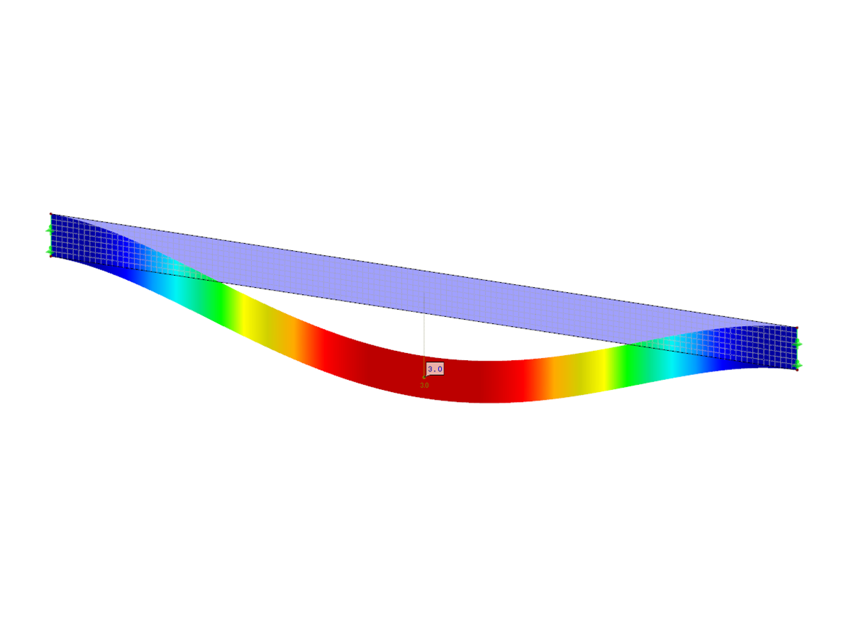
This feature helps you with the load application. You can have the required loading applied incrementally. This option is particularly suitable for your calculations according to the large deformation analysis. Furthermore, you can easily perform post‑critical analyses in RFEM.
The RF-MOVE/RSMOVE add-on module does not display any result windows: You can check the created load cases, including loads, in RFEM/RSTAB. Descriptions of the individual moving loads are created on the basis of the respective load increment number.
However, it is possible to modify the descriptions in RFEM/RSTAB. You can export all data in tables to MS Excel.
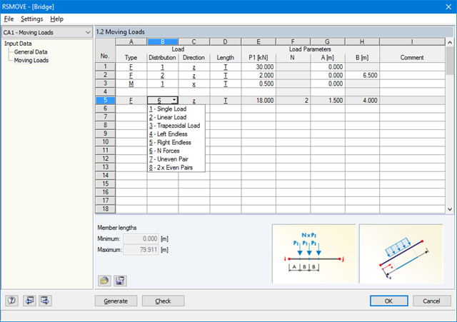
Sets of members with moving loads are selected graphically in the RFEM/RSTAB model. You can apply several different types of loads to one set of members at the same time.
By specifying the first load position, you can precisely display the load entering the runway of the continuous member. In the same way, it is possible to define whether a moving load consisting of various load applications is allowed to move beyond the end of continuous members (bridge) or not (crane runway).
The increment of the individual load positions is determined by the number of load cases generated for RFEM/RSTAB. You can also add loads to already existing RFEM/RSTAB load cases so that no additional superposition is required. Several load types are available, for example single, linear and trapezoidal loads as well as load pairs and several uniform concentrated loads.
It is possible to apply the loads in local and global directions. The application can refer to the true member length or to the projection in a global direction.
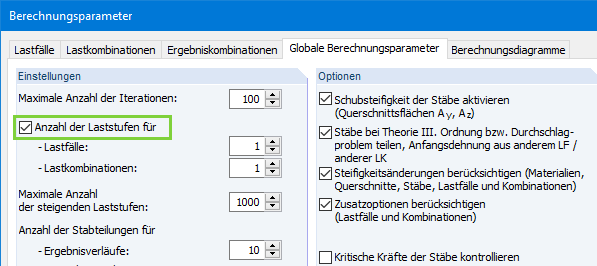
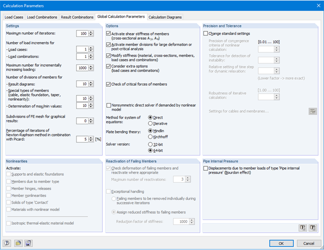
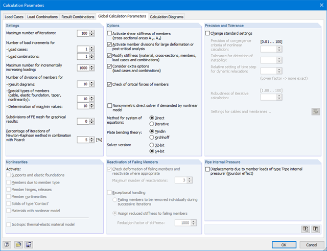
If the check box 'Number of load increments' is deactivated, the number of load increments will be determined automatically in RFEM to solve nonlinear tasks efficiently.
The method used is based on a heuristic algorithm.
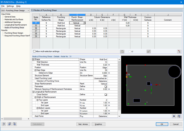
After opening the module, the materials and surface thicknesses defined in RFEM are preset. The nodes to be designed are automatically recognized but can also be modified by the user.
It is possible to consider openings in the area with risk of punching shear. The openings can be transferred from RFEM or specified only in RF‑PUNCH Pro so they do not effect the stiffnesses of the RFEM model.
The parameters of the longitudinal reinforcement are the number and direction of the layers and the concrete cover, specified separately for the top and bottom of the slab on a surface-by-surface basis.
The next input window allows you to define all additional details for nodes of punching shear.
The module recognizes the position of the punching node and automatically sets, whether the node is located in the center of the slab, on the slab edge or in the slab corner.
In addition, it is possible to set punching load, load increment factor β, and the existing longitudinal reinforcement. Optionally, the minimum moments can be activated for determining the required longitudinal reinforcement and enlarged column head.
To facilitate orientation, a slab is always displayed with the corresponding node of punching shear. You can also open the design program by HALFEN, a German producer of shear rails. All RFEM data can be imported to this program for further easy and effective processing.

- Import of relevant information and results from RFEM
- Integrated, editable material and section library
- The module extension EC2 for RFEM enables the design of reinforced concrete members according to EN 1992‑1‑1:2004 (Eurocode 2) and the following National Annexes:
-
 DIN EN 1992-1-1/NA/A1:2015-12 (Germany)
 -
 ÖNORM B 1992-1-1:2018-01 (Austria)
 -
 NBN EN 1992-1-1 ANB:2010 (Belgium)
 -
 BDS EN 1992-1-1:2005/NA:2011 (Bulgaria)
 -
 EN 1992-1-1 DK NA:2013 (Denmark)
 -
 NF EN 1992-1-1/NA:2016-03 (France)
 -
 SFS EN 1992-1-1/NA:2007-10 (Finland)
 -
 UNI EN 1992-1-1/NA:2007-07 (Italy)
 -
 LVS EN 1992-1-1:2005/NA:2014 (Latvia)
 -
 LST EN 1992-1-1:2005/NA:2011 (Lithuania)
 -
 MS EN 1992-1-1:2010 (Malaysia)
 -
 NEN-EN 1992-1-1+C2:2011/NB:2016 (Netherlands)
 - NS EN 1992-1 -1:2004-NA:2008 (Norway)
-
 PN EN 1992-1-1/NA:2010 (Poland)
 -
 NP EN 1992-1-1/NA:2010-02 (Portugal)
 -
 SR EN 1992-1-1:2004/NA:2008 (Romania)
 -
 SS EN 1992-1-1/NA:2008 (Sweden)
 -
 SS EN 1992-1-1/NA:2008-06 (Singapore)
 -
 STN EN 1992-1-1/NA:2008-06 (Slovakia)
 -
 SIST EN 1992-1-1:2005/A101:2006 (Slovenia)
 -
 UNE EN 1992-1-1/NA:2013 (Spain)
 -
 CSN EN 1992-1-1/NA:2016-05 (Czech Republic)
 -
 BS EN 1992-1-1:2004/NA:2005 (United Kingdom)
 -
 TKP EN 1992-1-1:2009 (Belarus)
 -
 CYS EN 1992-1-1:2004/NA:2009 (Cyprus)
-
In addition to the National Annexes (NA) listed above, you can define a specific NA, applying user‑defined limit values and parameters.
- Sensible and complete presetting of input parameters
- Punching design on columns, wall ends, and wall corners
- Optional arrangement of an enlarged column head
- Automatic recognition of the position of the punching node from the RFEM model
- Detection of curves or splines as boundary of the control perimeter
- Automatic consideration of all slab openings defined in the RFEM model
- Structure and graphical display of the control perimeter before calculation starts
- Qualitative determination of punching shear reinforcement
- Optional design with unsmoothed shear stress along the control perimeter that corresponds to the actual shear stress distribution in the FE model
- Determination of the load increment factor β via full-plastic shear distribution as constant factors according to EN 1992‑1‑1, Sect. 6.4.3 (3), based on EN 1992‑1‑1, Fig. 6.21N or by user‑defined specification
- Integration of design software by Halfen, a producer of shear rails
- Numerical and graphical display of results (3D, 2D, and in sections)
- Punching shear design with or without punching shear reinforcement
- Optional consideration of minimum moments according to EN 1992‑1‑1 when determining longitudinal reinforcement
- Design or analysis of longitudinal reinforcement
- Complete integration of results in the RFEM printout report
The loading can be applied incrementally. The increment option is especially useful for calculations according to the large deformation analysis. For members, you can consider shear deformations and apply internal forces to a deformed or undeformed structural system. In addition, RFEM allows you to perform post‑critical analyses.
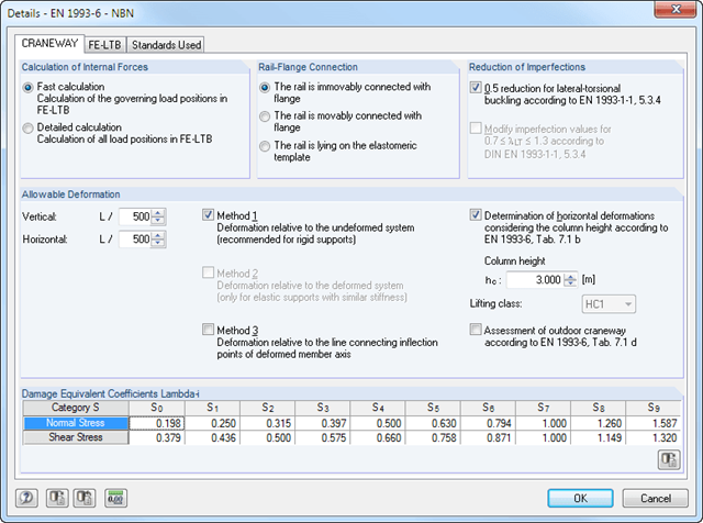
During the calculation, crane loads are generated in predefined distances as load cases of the crane runway. The load increment for cranes moving across the crane runway can be set individually.
The program analyzes all combinations of the respective limit states (ULS, fatigue, deformation, and support forces) for each crane position. In addition, there are comprehensive setting options for specification of the FE calculation, such as length of finite elements or break-off criteria.
The internal forces of a crane runway girder are calculated on an imperfect structural model according to the second-order analysis for torsional buckling.
Several methods are available for the eigenvalue analysis:
- Direct Methods
- The direct methods (Lanczos, roots of characteristic polynomial, subspace iteration method) are suitable for small to medium-sized models. These fast methods for equation solvers benefit from a lot of the computer memory (RAM). 64-bit systems use more memory so that even bigger structural systems can be calculated quickly.
- ICG iteration method (Incomplete Conjugate Gradient)
- This method requires only a small amount of memory. Eigenvalues are determined one after the other. It can be used to calculate large structural systems with few eigenvalues.
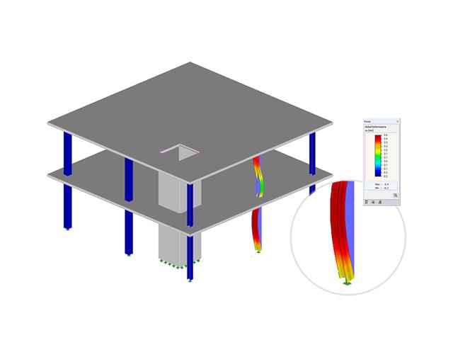
The RF-STABILITY add-on module can also perform the non-linear stability analysis. Also for nonlinear structures, results close to reality are provided. The critical load factor is determined by gradually increasing the loads of the underlying load case until the instability is reached. The load increment takes into account nonlinearities such as failing members, supports and foundations, and material nonlinearities.

You can select several methods that are available for the eigenvalue analysis:
- Direct Methods
- The direct methods (Lanczos [RFEM], roots of characteristic polynomial [RFEM], subspace iteration method [RFEM/RSTAB], and shifted inverse iteration [RSTAB]) are suitable for small to medium-sized models. You should only use these fast solver methods if your computer has a larger amount of memory (RAM).
- ICG Iteration Method (Incomplete Conjugate Gradient [RFEM])
- In contrast, this method only requires a small amount of memory. Eigenvalues are determined one after the other. It can be used to calculate large structural systems with few eigenvalues.
Use the Structure Stability add-on to perform a nonlinear stability analysis using the incremental method. This analysis delivers close-to-reality results also for nonlinear structures. The critical load factor is determined by gradually increasing the loads of the underlying load case until the instability is reached. The load increment takes into account nonlinearities such as failing members, supports and foundations, and material nonlinearities. After increasing the load, you can optionally perform a linear stability analysis on the last stable state in order to determine the stability mode.
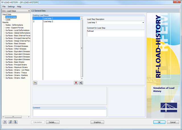
After defining the entire model and loading in RFEM, it is possible to enter load steps and descriptions in the 1.1 General Data window.
In Window 1.2 Loads, you can assign the load cases or load combinations to the different load increments. It is possible to multiply them by a load factor.
.png?mw=640&hash=31ebb9c47d4f8334d4a27ff248233fc0442a2e72)
- Simple definition of load increments
- Simple assignment of load cases and load combinations to load increments
- Consideration of plastic deformations (isotropic hardening behavior) of previous load increments
- Numerical and graphical display of results (deformations, support forces, internal forces, stresses, strains, and so on) for individual load increments
- Detailed printout report including result documentation for all load increments
- Calculation of models consisting of member, shell, and solid elements
- Import of axial forces from a load case or combination
- Non-linear stability analysis
- Optional consideration of axial forces from initial prestress
- Four equation solvers for effective calculation of various structural models
- Optional consideration of stiffness modifications in RFEM
- Calculation of buckling modes of unstable models
- Determination of stability mode greater than the user-defined load increment factor (Shift method)
- Optional determination of the mode shapes of unstable models (to identify the cause of instability)
- Visualization of stability mode
- Basis for analysis using imperfect equivalent structures in RF-IMP
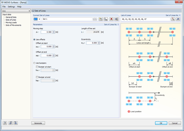
Surfaces with moving loads are selected graphically in the RFEM model. You can apply loads with several different sets of movement on one surface at the same time.
The 'lane' is defined by means of line sets. You can select them graphically in the model. In addition, you can enter the increment of the individual load steps. Several load types are available; for example, single, linear, rectangular, circular, and various axle loads. They can be applied in local and in global directions.
The different loads are summarized in load models. The module assigns defined load models to the sets of lines and creates individual load cases based on these data.