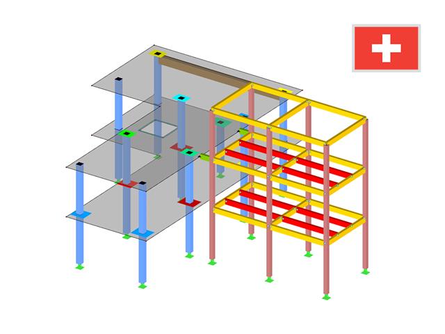
The material library already includes Swiss types of concrete and reinforcing steel available for design. However, you can always define other materials for the design according to SIA 262. The program performs the ultimate and the serviceability limit state design.
The crack width analysis can be performed using the design of Sigmas,adm, rebar spacing sL, or a direct calculation of crack widths according to the technical documentation D0182. Depending on the selected concrete type, the program determines the limit value Sigmas,adm according to D0182, Eq. 10.13; the upper limit is set by the design criterion fsd.
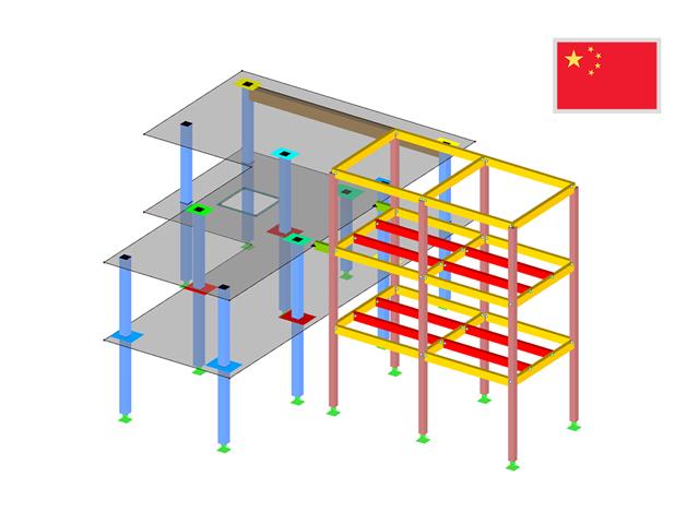
The material library already includes the Chinese types of concrete and reinforcing steel available for design. However, you can always define other materials for the design according to GB 50010.
In addition, it is possible consider the seismic design according to the standard GB 50011‑2010 (Code for seismic design of buildings).
- Design of tension, compression, bending, shear, combined internal forces, and torsion
- Stability analysis for flexural buckling, torsional buckling, and lateral-torsional buckling
- Optional application of discrete lateral supports to beams
- Deformation analysis (serviceability)
- Cross-section optimization
- Wide range of cross-sections available, such as rolled I-sections, channel sections, rectangular hollow sections, angles, T-sections. Welded sections: I-shaped (symmetrical and asymmetrical about major axis), channel sections (symmetrical about major axis), rectangular hollow sections (symmetrical and asymmetrical about major axis), angles, round pipes, and round bars
- Clearly arranged result tables
- Detailed result documentation including references to design equations of the used standard
- Various filter and sorting options of results, including result lists by member, cross-sections, x-location, or by load case, load and result combination
- Result table of member slenderness and governing internal forces
- Parts list with weight and solid specifications
- Seamless integration in RFEM/RSTAB
.png?mw=640&hash=721e09a7520480378145fa75eaabf5a5bed8f7e3)
- Full integration in RFEM/RSTAB including import of all relevant information and internal forces
- Determination of stress ranges for the available load cases and load or result combinations
- Free assignment of detail categories on the available stress points of the cross-section
- User-defined specification of damage equivalent factors
- Design of members and sets of members according to EN 1993-1-9
- Optimization of cross-sections with the option to transfer the data to RFEM/RSTAB
- Detailed result documentation with references to design equations used
- Various filter and sorting options of results, including result lists by member, cross-sections, x-location, or by load case, load and result combination
- Visualization of the design criterion on RFEM/RSTAB model
- Data export to MS Excel
- Full integration in RFEM/RSTAB with import of relevant internal forces
- Design checks for the elastic-elastic and elastic-plastic methods
- Graphical selection of members and sets of members for design
- Analysis for several load and design cases
- Design based on the buckling field parameters integrated in the cross-section library for the cross-section parts supported on one and both sides
- Optional determination of shear stresses according to comment on El. (745)
- Possibility to consider the weld thickness in the design of welded cross-sections, which has the effect of a shortening of the cross-section part width
- Cross-section optimization with the option to export modified cross-sections
- Design of member ends, members, nodal supports, nodes, and surfaces
- Consideration of specified design areas
- Check of cross-section dimensions
- Design according to EN 1995-1-1 (European Timber Standard) with the respective National Annexes + DIN 1052 + DSTV DIN EN 1993-1-8 + ANSI / AWC - NDS 2015 (US Standard)
- Design of various materials, such as steel, concrete, and others
- No necessary linking to specific standards
- Extensible library including timber fasteners (SIHGA, Sherpa, WÜRTH, Simpson StrongTie, KNAPP, PITZL) and steel fasteners (standardized connections in steel building design according to EC 3, M-connect, PFEIFER, TG-Technik)
- Ultimate load capacities of timber beams by the companies STEICO and Metsä Wood available in the library
- Connection to MS Excel
- Optimization of connecting elements (the most utilized element is calculated)
- Full integration in RFEM/RSTAB including import of all relevant internal forces
- Intelligent presetting of flexural buckling-specific design parameters
- Automatic determination of the distribution of internal forces and classification according to DIN 18800, Part 2
- Optional import of buckling lengths from the RF-STABILITY/RSBUCK add-on module. For this, a comfortable graphical selection of the relevant buckling mode is possible
- Optimizing Cross-Sections
- Optional calculation according to both design methods of DIN 18800, Part 2
- Automatic determination of the most unfavorable design location, also for tapered members
- Check of c/t-limit values according to DIN 18800, Part 1
- Design of any thin-walled RFEM/RSTAB or SHAPE-THIN section for compression and bending without interaction according to the elastic-plastic method
- Design of I-shaped rolled and welded sections, I-like sections, box sections, and pipes subjected to bending and compression with iteration according to the elastic-plastic method
- Clearly arranged, comprehensible design checks with all intermediate values in the short and long forms
- Parts list of members and sets of members
- Direct export of all results to MS Excel
- A manual with manually calculated examples
It is possible to perform the following designs:
- Equilibrium limit state design
- Uplift limit state design
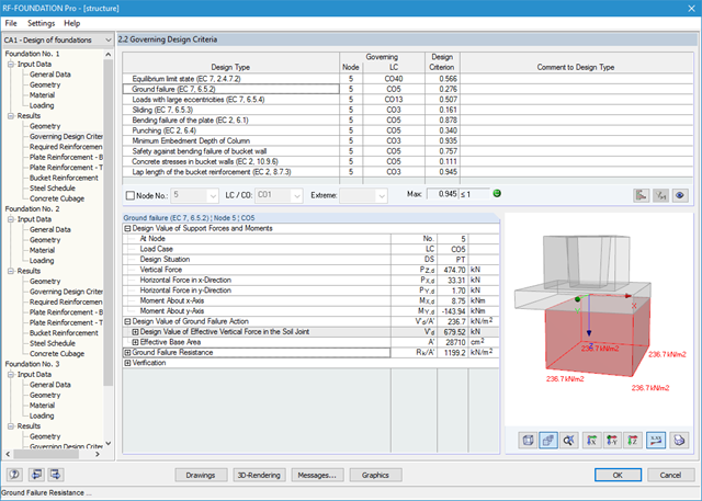
- Ground failure (soil contact pressure) design
- Strong eccentric loads design
- Design of foundation torsion and limitation of gaping joint
- Sliding design
- Settlement calculation
- Bending failure design of the plate and bucket
- Punching shear design
Foundation and bucket dimensions can be user-defined or determined by the module. You can edit the determined reinforcement manually. In this case, the designs are updated automatically.
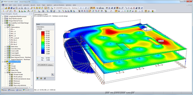
After the calculation, the module shows clearly arranged tables listing the results of the nonlinear calculation. All intermediate values are included in a comprehensible manner. Graphical representation of design ratios, deformations, concrete and reinforcing steel stresses, crack widths, crack depths, and crack spacing in RFEM facilitates a quick overview of critical or cracked areas.
Error messages or remarks concerning the calculation help you find design problems. Since the design results are displayed by surface or by point including all intermediate results, you can retrace all details of the calculation.
Due to the optional export of input or result tables to MS Excel, the data remain available for further use in other programs. The complete integration of results in the RFEM printout report guarantees verifiable structural design.
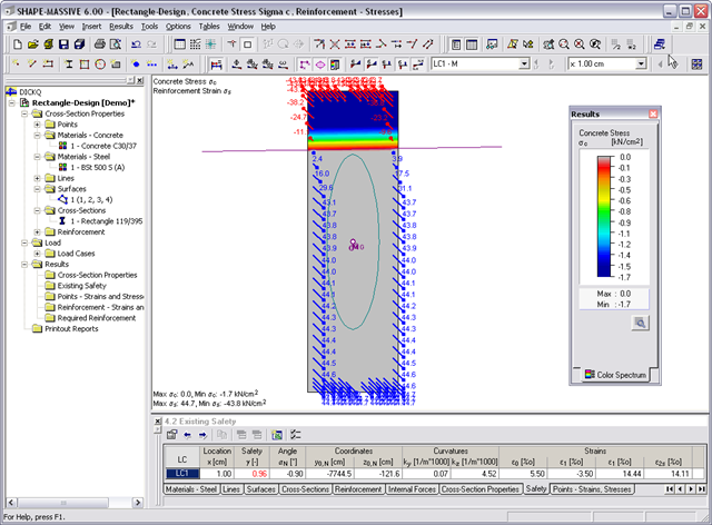
- Stresses σ and strains ε of concrete and reinforcement without considering concrete tensile strength (state II)
- Ultimate limit state design (existing safety) or design of defined internal forces
- Location of the neutral axis α0, y0,N, z0,N
- Curvatures ky, kz
- strain in the zero point ε0 and governing strains at the compression edge ε1 and at the tension edge ε2
- Governing steel strain ε2s
- Normal stresses σx due to axial force and bending
- Shear stresses τ due to shear force and torsion
- Equivalent stresses σv compared to limit stress
- Stress ratios related to equivalent stresses
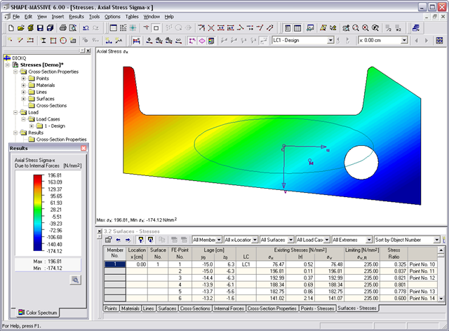
- Normal stress σx due to unit axial force N
- Shear stress τ due to unit shear forces Vy, Vz, Vu, Vv
- Normal stress σx due to unit momentsMy, Mz, Mu, Mv
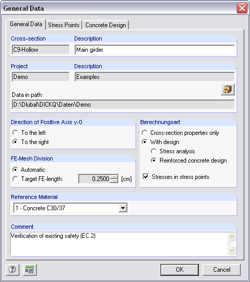
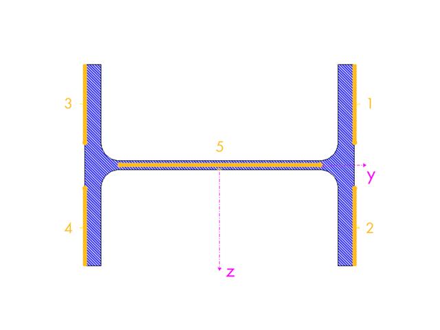
It is possible to freely model a cross-section using surfaces limited by polygonal lines, including openings and point areas (reinforcements). Alternatively, you can use the DXF interface to import the geometry. An extensive material library facilitates the modeling of composite cross-sections.
Definition of limit diameters and priorities allows for a curtailment of reinforcements. In addition, you can consider the respective concrete covers and prestresses.
After the calculation, the maximum stresses, stress ratios, and displacements are displayed by load case, surface, or grid points. The design ratio can be related to any kind of stress type. The current location is highlighted by color in the RFEM model.
In addition to the result evaluation in tables, it is possible to display the stresses and stress ratios graphically in the RFEM work window. For this, you can adjust the colors and values assigned in the panel.
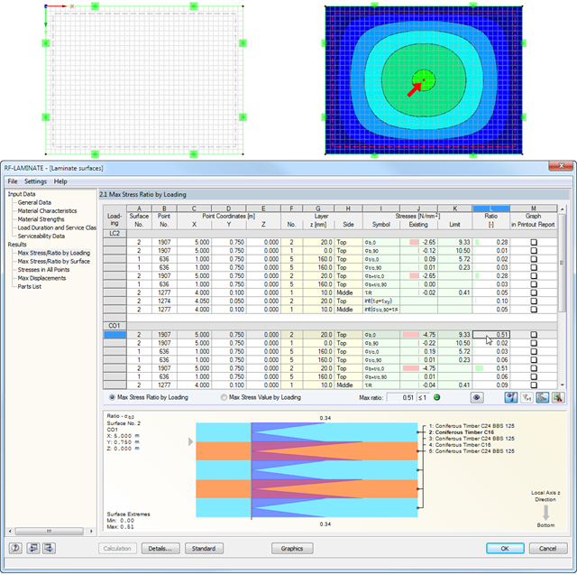
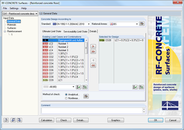
It is necessary to select load cases, load combinations, and result combinations for the ultimate and the serviceability limit state design. After selecting the surfaces to be designed, you can define the relevant material model.
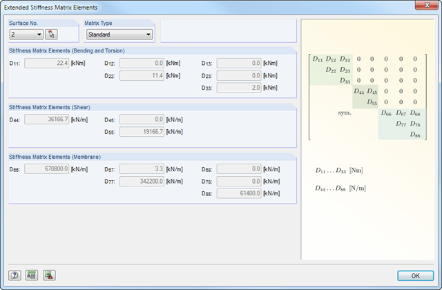
The structure of layers forming the basis for the stiffness calculation can vary. You can adjust the parameters defined by the selected material model according to your individual needs. The 3*3 matrix of the layers is modifiable as well. In this way completely free selection when generating the stiffnesses is provided.
The limit stresses of each layer are defined by the selected material. These values can be customized as well.
For reasons of result evaluation, clearly arranged result tables are available. The first window shows the maximum design ratios including the corresponding design of each designed load case, load combination, or result combination.
The other result windows list all detailed results sorted by specific subject in extendable tree menus. All intermediate results along the members can be displayed at any location. In this way, you can easily retrace how the module has performed the individual designs.
The complete module data are part of the RFEM/RSTAB printout report. You can select the report contents and extent specifically for the individual designs. The graphical result display of the governing design criteria in RFEM/RSTAB provides a quick overview of the design ratios of individual structural components.
It is necessary to enter material, load, and combination data in RFEM/RSTAB in compliance with the design concept specified by SIA 263.
The RFEM/RSTAB material library already contains the relevant materials for SIA. Furthermore, RFEM/RSTAB automatically creates the corresponding load combinations according to SIA 260. However, you can also create all the combinations manually in RFEM/RSTAB.
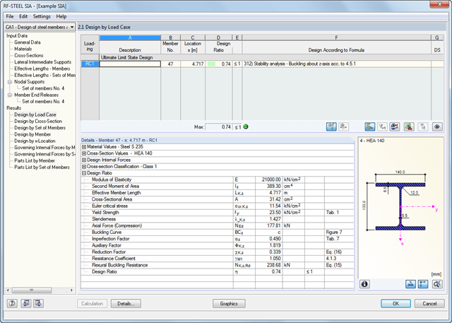
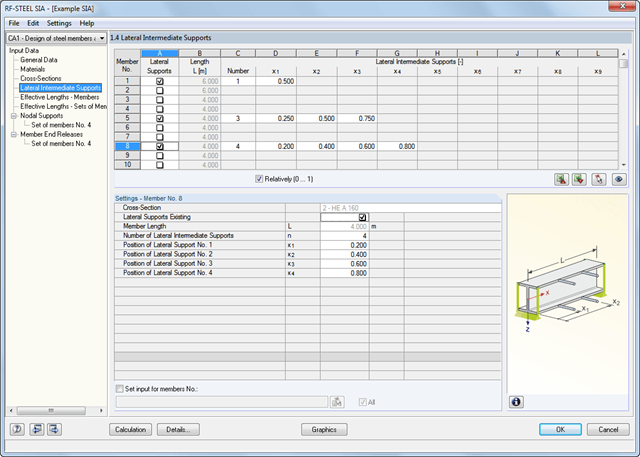
The RF-/STEEL SIA add-on module requires members and sets of members, as well as load cases, load combinations, and result combinations to be designed. In the next steps, you can adjust the preset definitions of lateral intermediate supports and effective lengths.
In the case of continuous members, it is possible to define individual support conditions and eccentricities of each intermediate node of single members. A special FEA tool then determines the critical loads and moments required for the stability analysis in these situations.
The program creates a reinforcement proposal for the top and the bottom plate reinforcement. The program searches automatically for the most favorable reinforcement combination, with a mat and added rebars. If required, the rebars are distributed across two reinforcement areas by curtailment. It is possible to modify the reinforcement proposal individually by:
- Application of another mat type
- Individual control of diameter and spacing of added rebars
- Free selection of reinforcement area widths
- Individual curtailment of reinforcements
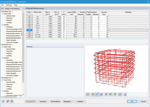
You can display the foundation in excellent rendering quality, including reinforcement. In the rendering, as well as in up to seven different dimensioned reinforcement drawings ready for construction, the module provides a solution proposal for bucket design. It is possible to modify the number, position, diameter, and spacing of used rebars here as well. You can also determine the shape of the applied links.
The dimensions of the foundation plate and bucket can be determined by the add-on module, or can be user-defined. Clearly arranged windows display the results of each performed design, including all intermediate values. They are covered in a reduced printout report providing a verifiable structural analysis.
The material library already includes German types of concrete and reinforcing steel available for design. However, you can always define other materials for the design according to DIN 1045‑1.
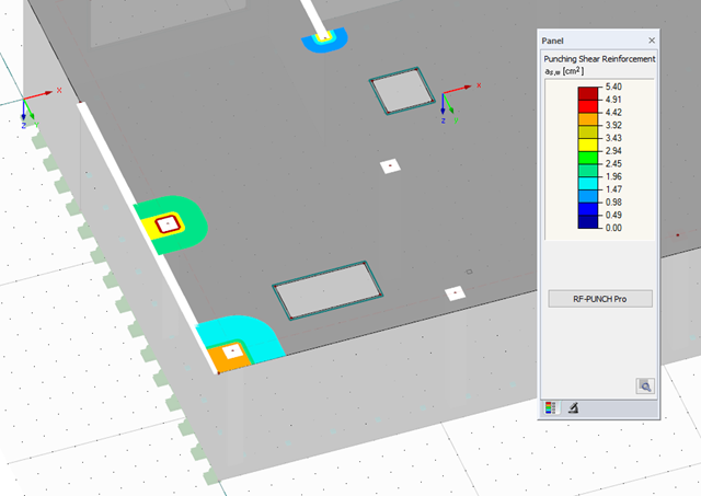
After the design, the punching checks are presented clearly and with all result details, so that traceability is guaranteed at all times. The provided and allowable shear stresses for the shear resistance design of a slab as well as various perimeters and reinforcement ratios are represented in detail. If necessary, a clarifying note is displayed.
The next result window lists the required longitudinal or punching reinforcement of each analyzed node. An explanatory graphic is also available. The design results can be clearly displayed with values in the work window. Furthermore, you can add all result tables and graphics into the global printout report of RFEM, which guarantees coherent documentation.
The deformation analysis with RF-CONCRETE Deflect can be activated in the settings for the analytical serviceability limit state design in the RF-CONCRETE Surfaces module. Consideration of long-term effects (creep and shrinkage) and tension stiffening between cracks can also be managed in the dialog box above. The creep coefficient and shrinkage strain are calculated using the specified input parameters or defined individually.
You can specify the deformation limit value individually for each surface or for an entire surface group. The max. deformation is defined as the allowable limit value. In addition, you have to specify whether the undeformed or the deformed system is to be used for the design check.