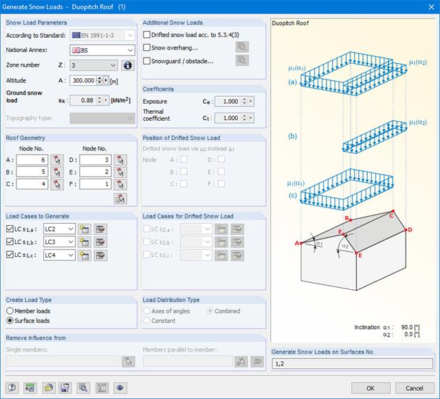
The snow load generator can generate snow loads as member loads or surface loads.
Additional snow loads such as drifted snow loads, snow overhangs, and snow guards can be taken into account as well.
The following standards are available:
-
 EN 1991-1-3 (incl. National Annexes)
 -
 DIN 1055-5
 -
 CTE DB-SE-AE
 -
 ASCE/SEI 7-16

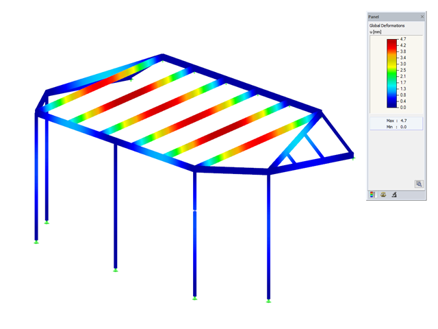
Wind loads can be automatically generated as member loads or area loads on the following structural components (optional with internal pressure for open buildings):
- Vertical walls
- Flat roofs
- Monopitch roofs
- Duopitch/troughed roofs
- Vertical walls with roof
The following standards are available:
-
EN 1991-1-3 (incl. National Annexes)
-
DIN 1055-4
-
CTE DB-SE-AE
-
ASCE/SEI 7-16
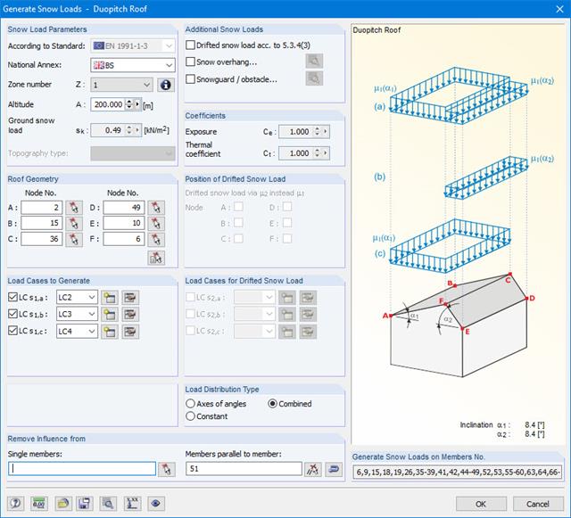
Snow loads can be generated as member loads on flat/monopitch roofs and duopitch roofs.
Additional snow loads such as drifted snow loads, snow overhangs, and snow guards can be taken into account as well.
The following standards are available:
-
EN 1991-1-3 (incl. National Annexes)
-
DIN 1055-5
-
CTE DB-SE-AE
-
ASCE/SEI 7-16
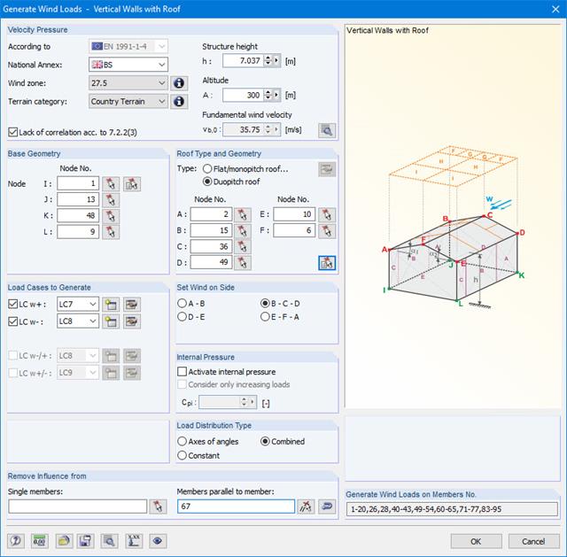
Wind loads can be automatically generated as member loads on the following structural components (optional with internal pressure for open buildings):
- Vertical walls
- Flat roofs
- Monopitch roofs
- Duopitch/troughed roofs
- Vertical walls with roof
The following standards are available:
-
EN 1991-1-3 (incl. National Annexes)
-
DIN 1055-4
-
CTE DB-SE-AE
-
ASCE/SEI 7-16
After the calculation, the module displays results in clearly arranged result tables. All intermediate values (for example, governing internal forces, adjustment factors, and so on) can be included in order to make the design more transparent. The results are sorted by load case, cross-section, set of members, and members. If the analysis fails, the affected cross-sections can be modified in an optimization process.
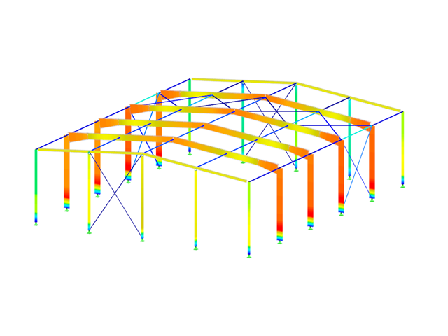
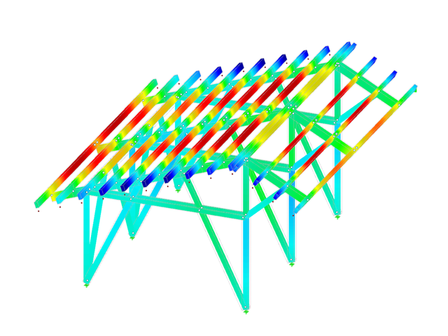
The design ratio is represented with different colors in the RFEM/RSTAB model. This way, you can quickly recognize critical or oversized areas of the cross-section. Furthermore, result diagrams displayed on the member or set of members ensure targeted evaluation.
In addition to the input and result data, including design details displayed in tables, you can add all graphics into the printout report. This way, comprehensible and clearly arranged documentation is guaranteed. You can select the report contents and extent specifically for the individual designs.
The first result window shows the maximum design ratios with the corresponding design for each designed load case and combination.
The other windows show all detailed results sorted by specific topics. It is possible to display all intermediate results of each location along the members. In this way, you can easily retrace how the module has performed the individual designs.
The complete module data are part of the RFEM/RSTAB printout report. You can select the report contents and extent specifically for the individual designs.
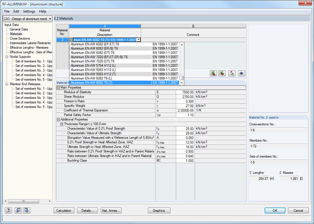
The data specified in RFEM/RSTAB concerning material, loads, and load combinations must comply with the design concept of the Eurocode. The RFEM/RSTAB material library already contains the relevant materials. Furthermore, RFEM/RSTAB allows for automatic creation of load and result combinations in accordance with the Eurocode. It is also possible to create the combinations manually.
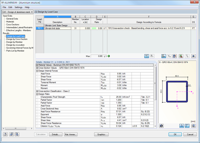
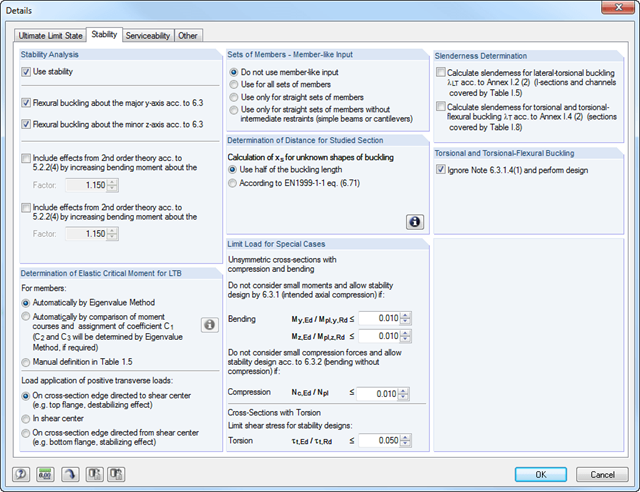
In the RF-/ALUMINUM add-on module, you must first select the members and sets of members to be designed, as well as the load cases, load combinations, and result combinations. In the subsequent input windows, you can adjust preset definitions of lateral intermediate supports and effective lengths.
When using continuous members, you can define individual support conditions and eccentricities for each intermediate node of the single members. A special FEA tool determines the critical loads and moments required for the stability analysis.
The first window shows the maximum design ratios including the corresponding design of each designed load case, load combination, or result combination.
The other result windows list all detailed results sorted by specific subject in extendable tree menus. All intermediate results along the members can be displayed at any location. In this way, you can easily retrace how the module has performed the individual designs.
The complete module data are part of the RFEM/RSTAB printout report. You can select the report contents and extent specifically for the individual designs.
It is necessary to enter material, load, and combination data in RFEM/RSTAB in compliance with the design concept specified by GB 50017. The RFEM/RSTAB material library already contains the relevant materials.
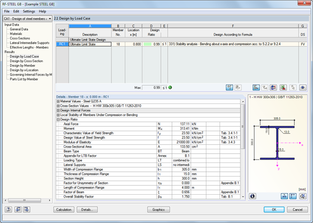
The RF-/STEEL GB add-on module requires members and sets of members, as well as load cases, load combinations, and result combinations to be designed.
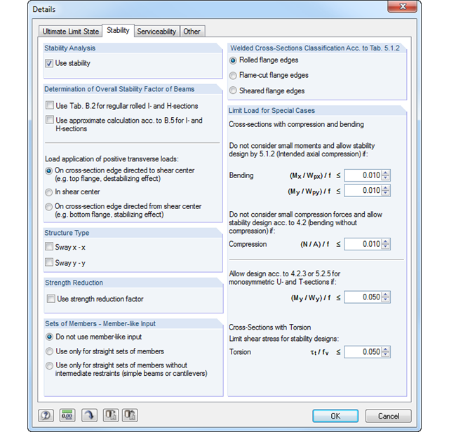
In the subsequent input windows, you can adjust preset definitions of lateral intermediate supports and effective lengths. This setting is then used by the program to determine the critical loads and moments required for the stability analysis in these situations.
- Design of tension, compression, bending, shear, and combined internal forces
- Stability analysis for flexural buckling and lateral-torsional buckling
- Automatic determination of critical buckling loads and overall stability factors for lateral-torsional buckling according to Annex B
- Optional application of discrete lateral supports to beams
- Automatic local stability analysis and check of plastic design criteria of a cross-section
- Deformation analysis (serviceability)
- Cross-section optimization
- Wide range of cross-sections available, such as rolled I-sections, channel sections, rectangular hollow sections, angles, T-sections. Welded sections: I-shaped (symmetrical and asymmetrical about major axis), channel sections (symmetrical about major axis), rectangular hollow sections (symmetrical and asymmetrical about major axis), angles, round pipes, and round bars
- Clearly arranged result tables
- Detailed result documentation including references to design equations of the used standard
- Various filter and sorting options of results, including result lists by member, cross-sections, x-location, or by load case, load and result combination
- Result table of member slenderness and governing internal forces
- Parts list with weight and solid specifications
- Seamless integration in RFEM/RSTAB
- Design of tension, compression, bending, shear, and combined internal forces
- Stability analysis for flexural buckling, torsional buckling, and lateral-torsional buckling
- Automatic determination of critical buckling loads and critical moment for lateral-torsional buckling by means of integrated FEA program (eigenvalue analysis) from boundary conditions of loads and supports
- Optional application of discrete lateral supports to beams
- Automatic or manual cross-section classification
- Integration of parameters from National Annexes (NA) of the following countries:
-
DIN EN 1999-1-1/NA:2010-12 (Germany)
-
 NBN EN 1999-1-1/ANB:2011-03 (Belgium)
 -
 DK EN 1999-1-1/NA:2013-05 (Denmark)
 -
 SFS EN 1999-1-1/NA:2016-12 (Finland)
 -
 ELOT EN 1999-1-1/NA:2010-11 (Greece)
 -
 IS EN 1999-1-1/NA:2010-03 (Ireland)
 -
 UNI EN 1999-1-1/NA:2011-02 (Italy)
 -
 LST EN 1999-1-1/NA:2011-09 (Lithuania)
 -
 UNI EN 1999-1-1/NA:2011-02 (Italy)
 -
 NEN EN 1999-1-1/NB:2011-12 (Netherlands)
 -
 PN EN 1999-1-1/NA:2011-01 (Poland)
 -
 SS EN 1999-1-1/NA:2011-04 (Sweden)
 -
 STN EN 1999-1-1/NA:2010-01 (Slovakia)
 -
 BS EN 1999-1-1/NA:2009 (the United Kingdom)
 -
 STN EN 1999-1-1/NA:2009-02 (Slovakia)
 -
 CYS EN 1999-1-1/NA:2009-07 (Cyprus)
-
- Serviceability limit state design for characteristic, frequent, or quasi-permanent design situation
- Consideration of transverse welds
- Variety of cross-sections provided; for example, I‑sections, C‑sections, rectangular hollow sections, square sections, angles with equal and unequal legs, flat steel, round bars
- Clearly arranged result tables
- Automatic cross-section optimization
- Detailed result documentation with references to the design equations used and described in the standard
- Filter and sorting options for results, including result lists by member, cross‑section, and x‑location, or by load cases, load combinations, and result combinations
- Result window of member slenderness and governing internal forces
- Parts list with weight and solid specifications
- Seamless integration in RFEM/RSTAB
- Metric and imperial units
The cross-section resistance design analyzes tension and compression along the grain, bending, bending and tension/compression as well as the strength in shear due to shear force.
The design of structural components at risk of buckling or lateral buckling is performed according to the Equivalent Member Method and considers the systematic axial compression, bending with and without compression force as well as bending and tension. The deflection of inner spans and cantilevers is compared to the maximum allowable deflection.
Separate design cases allow for a flexible and stability analysis of members, sets of members, and loads.
Design-relevant parameters such as such as stability analysis, load duration in case of fire, member slendernesses, and limit deflection can be adjusted as desired.
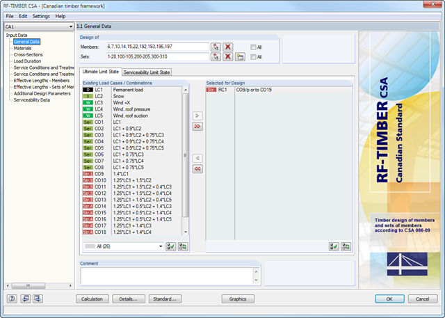
After opening the add-on module, it is necessary to select the members/sets of members, load cases, load or result combinations for the ultimate and the serviceability limit state design. The materials from RFEM/RSTAB are preset and can be adjusted in RF-/TIMBER CSA. Material properties listed in the respective standard are included in the material library.
When checking the cross-sections, you can specify whether to consider a cross-section selected in RFEM/RSTAB, or a modified cross-section. Then, you can define the load duration classes, the moisture service conditions, and timber treatment.
The deformation analysis requires the reference lengths of the relevant members and sets of members. Furthermore, you can define a specific direction of deflection, precamber and the beam type.
For fire resistance design, you can define the charring sides of a member or set of members.
- Design of members and continuous members for tension, compression, bending, shear, and combined internal forces
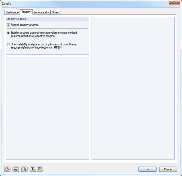
- Stability analysis for lateral-torsional buckling and buckling according to the equivalent member method or the second order analysis
- Serviceability limit state design by limitation of deflections
- Free configuration of charring time and charring rates, as well as free choice of charring sides for fire design
- Design of tapered and curved beams consisting of glulam timber
- Material and cross‑section library based on the Canadian standard
- User-defined entry of rectangular and circular cross-sections
- Automatic cross-section optimization
- Optional import of buckling lengths from the RF-STABILITY/RSBUCK module
- Detailed result documentation including references to design equations of the used standard
- Various filtering and sorting options of results
- Consideration of moisture service conditions
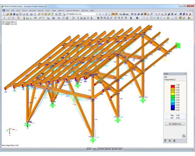
- Visualization of design criterion on RFEM/RSTAB model
- Data export to MS Excel
- Units metric and imperial
All results can be evaluated and visualized in an appealing numerical and graphical form. Selection functions facilitate the targeted evaluation.
The printout report corresponds to the high standards of RFEM and rstab/rstab-9/what-is-rstab RSTAB. Modifications are updated automatically.

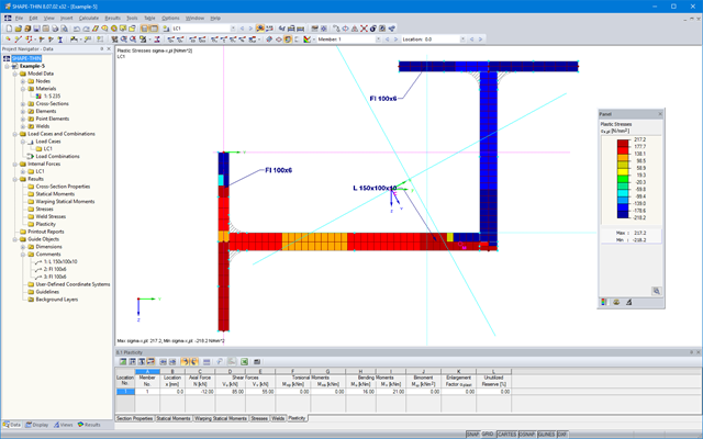
SHAPE-THIN calculates all relevant cross‑section properties, including plastic limit internal forces. Overlapping areas are set close to reality. If cross-sections consist of different materials, SHAPE‑THIN determines the effective cross‑section properties with respect to the reference material.
In addition to the elastic stress analysis, you can perform the plastic design including interaction of internal forces for any cross‑section shape. The plastic interaction design is carried out according to the Simplex Method. You can select the yield hypothesis according to Tresca or von Mises.
SHAPE-THIN performs a cross-section classification according to EN 1993-1-1 and EN 1999-1-1. For steel cross-sections of cross-section class 4, the program determines effective widths for unstiffened or stiffened buckling panels according to EN 1993-1-1 and EN 1993-1-5. For aluminum cross-sections of cross-section class 4, the program calculates effective thicknesses according to EN 1999-1-1.
Optionally, SHAPE‑THIN checks the limit c/t-values in compliance with the design methods el‑el, el‑pl, or pl‑pl according to DIN 18800. The c/t-zones of elements connected in the same direction are recognized automatically.

SHAPE-THIN includes an extensive library of rolled and parameterized cross-sections. They can be composed or supplemented by new elements. It is possible to model a section consisting of different materials.
Graphical tools and functions allow for modeling complex section shapes in the usual way common for CAD programs. The graphical entry provides the option of setting point elements, fillet welds, arcs, parameterized rectangular and circular sections, ellipses, elliptical arcs, parabolas, hyperbolas, spline, and NURBS. Alternatively, it is possible to import a DXF file that is used as the basis for further modeling. You can also use guidelines for modeling.
Furthermore, parameterized input allows you to enter model and load data in a specific way so they depend on certain variables.
Elements can be divided or attached to other objects graphically. SHAPE-THIN automatically divides the elements and provides for an uninterrupted shear flow by introducing dummy elements. In the case of dummy elements, you can define a specific thickness to control the shear transfer.

SHAPE-THIN determines the section properties and stresses of any open, closed, built-up, or non-connected cross-sections.
- Section Properties
- Cross-sectional area A
- Shear areas Ay, Az, Au, and Av
- Centroid position yS, zS
- moments of area 2 degrees Iy, Iz, Iyz, Iu, Iv, Ip, Ip,M
- Radii of gyration iy, iz, iyz, iu, iv, ip, ip,M
- Inclination of principal axes α
- Cross-section weight G
- Cross-section perimeter U
- torsional constants of area degrees IT, IT,St.Venant, IT,Bredt, IT,s
- Location of the shear center yM, zM
- Warping constants Iω,S, Iω,M or Iω,D for lateral restraint
- Max/min section moduli Sy, Sz, Su, Sv, Sω,M with locations
- Section ranges ru, rv, rM,u, rM,v
- Reduction factor λM
- Plastic Cross-Section Properties
- Axial force Npl,d
- Shear forces Vpl,y,d, Vpl,z,d, Vpl,u,d, Vpl,v,d
- Bending moments Mpl,y,d, Mpl,z,d, Mpl,u,d, Mpl,v,d
- Section moduli Zy, Zz, Zu, Zv
- Shear areas Apl,y, Apl,z, Apl,u, Apl,v
- Position of area bisecting axes fu, fv,
- Display of the inertia ellipse
- First moments of area Qu, Qv, Qy, Qz with location of maxima and specification of shear flow
- Warping coordinates ωM
- moments of area (warping areas) Sω,M
- Cell areas Am of closed cross-sections
- Normal stresses σx due to axial force, bending moments, and warping bimoment
- Shear stresses τ from shear forces as well as primary and secondary torsional moments
- Equivalent stresses σv with customizable factor for shear stresses
- Stress ratios, related to limit stresses
- Stresses for element edges or center lines
- Weld stresses in fillet welds
- Section properties of non-connected cross-sections (cores of high-rise buildings, composite sections)
- Shear wall shear forces due to bending and torsion
- Plastic capacity design with determination of the enlargement factor αpl
- Check of the c/t-ratios following the design methods el-el, el-pl or pl-pl according to DIN 18800
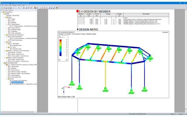
The first results window shows the maximum design ratios with the corresponding design of each designed load case, load combination, or result combination.
The other result windows list all detailed results sorted by specific subject in extendable tree menus. All intermediate results along a member can be displayed at any location. In this way, you can easily retrace how the module has performed the individual designs.
The complete data from the module are part of the RFEM/RSTAB printout report.
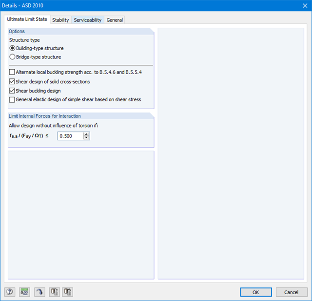
First, it is necessary to decide whether to perform design according to ASD or LRFD. Then, you can enter the load cases, load combinations, and result combinations to be designed. Load combinations according to ASCE 7 can be generated either manually or automatically in RFEM/RSTAB.
Further specifications include presetting of lateral intermediate supports, effective lengths, and other standard-specific design parameters. When using continuous members, it is possible to define individual support conditions and eccentricities at each intermediate node of the single members. A special FEA tool then internally determines the effective radii of gyration required for the stability analysis for these situations.
- Design of members and sets of members for tension, compression, bending, shear, torsion, and combined internal forces
- Stability analysis of buckling and lateral-torsional buckling
- Automatic determination of effective radius of gyration by special integrated FEA software (eigenvalue analysis) for general loading and support conditions
- Alternative analytical calculation of effective radius of gyration for standard situations
- Optional application of discrete lateral supports to beams
- Definition of nodal supports for sets of members
- Serviceability limit state design (deflection)
- Cross-section optimization
- A wide range of available cross-sections, such as rolled I-sections, channel sections, T-sections, angles, rectangular and circular hollow sections, round bars, and many others.
- Detailed result documentation including references to design equations of the used standard
- Various filter and sorting options of results, including result lists by member, cross-sections, and x-location, or by load case, load and result combination
- Result table of member slenderness and governing internal forces
- Metric and imperial units

- Modeling of the cross-section via elements, sections, arcs, and point elements
- Expansible library of material properties, yield strengths, and limit stresses
- Section properties of open, closed, or non-connected cross-sections
- Ideal section properties of cross-sections consisting of different materials
- Determination of weld stresses in fillet welds
- Stress analysis including design of primary and secondary torsion
- Check of c/t-ratios
- Effective cross-sections according to
- EN 1993-1-5 (including stiffened buckling panels according to Section 4.5)
-
EN 1993-1-3
-
EN 1999-1-1
-
to DIN 18800-2
- Classification according to
-
EN 1993-1-1
-
EN 1999-1-1
-
- Interface with MS Excel to import and export tables
- Printout report
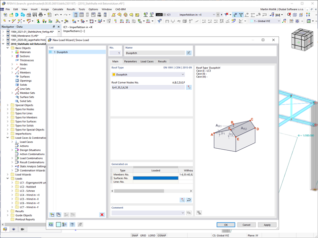
Do your structures also have to withstand snowfall? Use the Snow Load Wizard to generate snow loads as member loads or surface loads.
The following standards are available:
-
EN 1991-1-3 (incl. National Annexes)
-
ASCE 7
-
 NBC
NBC -
 SIA 261
 -
CTE DB-SE-AE
-
 GB 50009
 -
 IS 875

Wind loads are also not a problem in your design. You can automatically generate wind loads as member loads or area loads (RFEM) on the following structural components:
- Vertical walls
- Flat roofs
- Monopitch roofs
- Duopitch/troughed roofs
- Vertical walls with duopitch roof
- Vertical walls with flat/monopitch roof
The following standards are available to you:
-
EN 1991-1-4 (including National Annexes)
-
ASCE 7
-
CTE DB-SE-AE
-
GB 50009

- A wide range of available sections, such as rolled I-sections; channel sections; T-sections; angles; rectangular and circular hollow sections; round bars; symmetrical and asymmetrical, parametric I-, T-, and angle sections; built-up cross-sections (suitability for design depends on the selected standard)
- Design of general RSECTION cross-sections (depending on the design formats available in the respective standard); for example, equivalent stress design
- Design of tapered members (design method depending on the standard)
- Adjustment of the essential design factors and standard parameters is possible
- Flexibility due to detailed setting options for basis and extent of calculations
- Fast and clear results output for an immediate overview of the result distribution after the design
- Detailed output of the design results and essential formulas (comprehensible and verifiable result path)
- Numerical results clearly arranged in tables and graphical display of the results in the model
- Integration of the output into the RFEM/RSTAB printout report

- Design of tension, compression, bending, shear, torsion, and combined internal forces
- Tension design with consideration of a reduced section area (for example, hole weakening)
- Automatic classification of cross-sections to check local buckling
- Internal forces from the calculation with Torsional Warping (7 DOF) are taken into account by means of the equivalent stress check (currently not yet for the design standard ADM 2020).
- Design of cross-sections of Class 4 with effective cross-section properties according to EN 1993‑1‑5 (licenses for RSECTION and Effective Sections are required for the RSECTION cross-sections)
- Shear buckling check with consideration of transverse stiffeners

- Stability analyses for flexural buckling, torsional buckling, and flexural-torsional buckling under compression
- Lateral-torsional buckling analysis of the structural components subjected to moment loading
- Import of the effective lengths from the calculation using the Structure Stability add-on
- Graphical input and check of the defined nodal supports and effective lengths for stability analysis
- Depending on the standard, a choice between user-defined input of Mcr, analytical method from the standard, and use of internal eigenvalue solver
- Consideration of a shear panel and a rotational restraint when using the eigenvalue solver
- Graphical display of a mode shape if the eigenvalue solver was used
- Stability analysis of structural components with the combined compression and bending stress, depending on the design standard
- Comprehensible calculation of all necessary coefficients, such as interaction factors
- Alternative consideration of all effects for the stability analysis when determining internal forces in RFEM/RSTAB (second-order analysis, imperfections, stiffness reduction, possibly in combination with the Torsional Warping (7 DOF) add-on)

- A wide range of cross-sections, such as rectangular sections, square sections, T‑sections, circular sections, built-up cross-sections, irregular parametric cross-sections, and many others (suitability for design depends on the selected standard)
- Design of cross-laminated timber (CLT)
- Design of timber-based materials and laminated veneer lumber according to EC 5
- Design of tapered and curved members (design method according to the standard)
- Adjustment of the essential design factors and standard parameters is possible
- Flexibility due to detailed setting options for basis and extent of calculations
- Fast and clear results output for an immediate overview of the result distribution after the design
- Detailed output of the design results and essential formulas (comprehensible and verifiable result path)
- Numerical results clearly arranged in tables and graphical display of the results in the model
- Integration of the output into the RFEM/RSTAB printout report

- Arbitrary definition of the charring time
- Option to calculate with or without adhesion of the layer for surface structures (cross-laminated timber)
- Free user-defined specification of the fire parameters
- Consideration of Different Effective Lengths in Fire Resistance Design
- Optional design "Compression perpendicular to grain"
- Graphical result display integrated in RFEM/RSTAB, such as a design ratio
- Complete integration of the results into the RFEM/RSTAB printout report

Did you use the eigenvalue solver of the add-on to determine the critical load factor within the stability analysis? If so, you can then display the governing mode shape of the object to be designed as a result. The eigenvalue solver is available here for the lateral-torsional buckling analysis, depending on the design standard used.