
The program does a lot of work for you. For example, the load or result combinations required for the serviceability limit state are generated and calculated in RFEM/RSTAB. You can select these design situations for the deflection analysis in the Aluminum Design add-on. Depending on the specified precamber and reference system, the program determines the deformation values at each location of a member. They are then compared to the limit values.
You can specify the deformation limit value individually for each structural component in Serviceability Configuration. In this case, you define the maximum deformation depending on the reference length as the allowable limit value. By defining design supports, you can segment the components. In this way, you can determine the corresponding reference length automatically for each design direction.
And that's not all. Based on the position of the assigned design supports, the program allows you to automatically determine the distinction between beams and cantilevers. The limit value is thus determined accordingly.

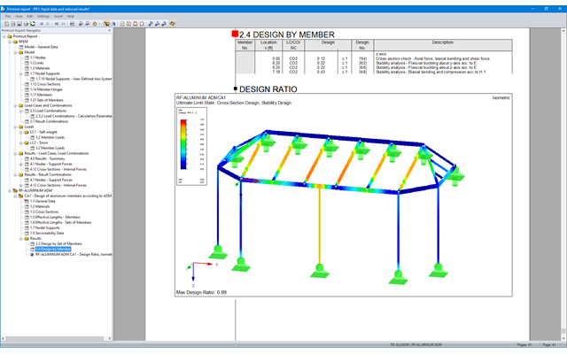
You can find the serviceability limit state design checks in the result tables of the Aluminum Design add-on. They are already fully integrated there. You have the option to display the design results with all the details at each location of the designed members. You can also use graphics with the result diagrams of the design ratios.
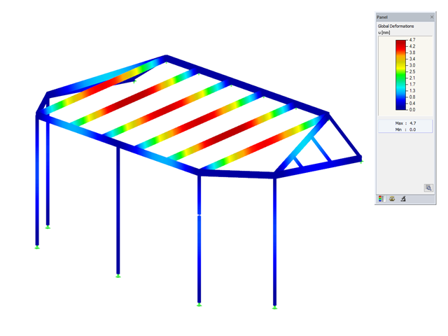
You can integrate all result tables and graphics into the global printout report of RFEM/RSTAB as a part of the aluminum design results. RFEM/RSTAB also allows you to display and document the deformations of the entire structure independently of the add-on.
When calculating the deflection limit, you have to consider certain reference lengths. You can define these reference lengths and the segments to be checked independently of each other, depending on the direction. For this, define design supports at the intermediate nodes of a member and assign them to the respective direction for the deformation analysis. Thus, the segments are created where you can define a precamber for each direction and segment.

Do you prefer it clear? So do we! That's why all performed design checks for the design standard are displayed for you in a clear way. You determine a design criterion for each design check. You get design details, which include the initial values, intermediate results, and final results, arranged in a structured way for each design check. You can find the calculation process with the applied formulas, standard sources, and results in great detail in an information window in the design details.

As usual, you enter the structural system and calculate the internal forces in the programs RFEM and RSTAB. You have unlimited access to the extensive material and cross-section libraries. Did you know that you can create general cross-sections using the RSECTION program? That saves you a lot of work.
Don't be afraid of additional windows and input chaos! Aluminum Design is completely integrated into the main programs and automatically takes into account the structure and the available calculation results. You can directly assign further entries for the aluminum design, such as effective lengths, cross-section reductions, or design parameters, to the objects to be designed. You can simply and efficiently select the elements graphically using the [Select] function.

- A wide range of available sections, such as rolled I-sections; channel sections; T-sections; angles; rectangular and circular hollow sections; round bars; symmetrical and asymmetrical, parametric I-, T-, and angle sections; built-up cross-sections (suitability for design depends on the selected standard)
- Design of general RSECTION cross-sections (depending on the design formats available in the respective standard); for example, equivalent stress design
- Design of tapered members (design method depending on the standard)
- Adjustment of the essential design factors and standard parameters is possible
- Flexibility due to detailed setting options for basis and extent of calculations
- Fast and clear results output for an immediate overview of the result distribution after the design
- Detailed output of the design results and essential formulas (comprehensible and verifiable result path)
- Numerical results clearly arranged in tables and graphical display of the results in the model
- Integration of the output into the RFEM/RSTAB printout report

- Calculation of deflections and comparison with the normative or manually adjusted limit values
- Consideration of a precamber for the deflection analysis
- Different limit values are possible, depending on the design situation type
- Manual Adjustment of Reference Lengths and Segmentation by Direction
- Calculation of deflections related to the initial structure or to the deformed structure
- Further detailed design checks depending on the selected design standard (for example, vibration design according to EN 1999‑1‑1, 7.2.3)
- Graphical result display integrated in RFEM/RSTAB; for example, the design ratio of a limit value, or the deformation or the sag
- Complete integration of the results into the RFEM/RSTAB printout report

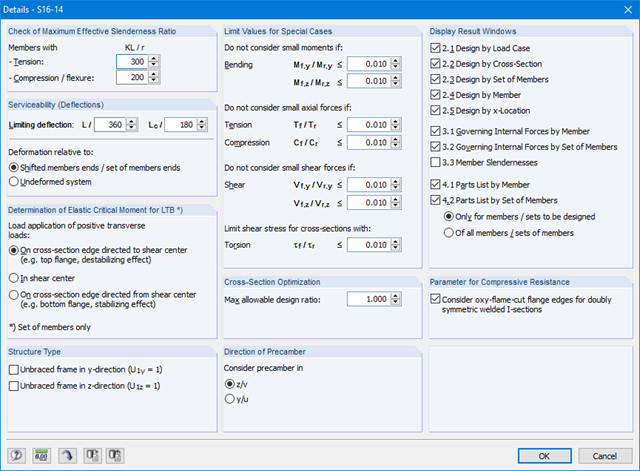
Note that the definition of the effective lengths in the Aluminum Design add-on is an essential requirement for the stability analysis. For this, define the nodal supports and effective length factors in the input dialog box. Do you want to clearly document the nodal supports and the resulting segments with the associated effective length factors? To check the input data, it is best for you to use the graphic display in the RFEM/RSTAB work window. Thus, you can comprehend the design at any time with minimum effort.

- Design of tension, compression, bending, shear, torsion, and combined internal forces
- Tension design with consideration of a reduced section area (for example, hole weakening)
- Automatic classification of cross-sections to check local buckling
- Internal forces from the calculation with Torsional Warping (7 DOF) are taken into account by means of the equivalent stress check (currently not yet for the design standard ADM 2020).
- Design of cross-sections of Class 4 with effective cross-section properties according to EN 1993‑1‑5 (licenses for RSECTION and Effective Sections are required for the RSECTION cross-sections)
- Shear buckling check with consideration of transverse stiffeners
You can find the design checks displayed in tables in the Aluminum Design add-on. Moreover, you can display the distribution of the design ratios graphically. Extensive filter options are available for you both in the table as well as in the graphical output. You can thus specifically display the desired design checks by limit state or design type in the program.
- Design of members and sets of members for tension, compression, bending, shear, combined internal forces, and torsion
- Stability analysis of buckling, torsional, and flexural-torsional buckling
- Automatic determination of critical buckling loads and critical buckling moments for general load applications and support conditions by means of a special FEA program (eigenvalue analysis) integrated in the module
- Alternative analytical calculation of the critical buckling moment for standard situations
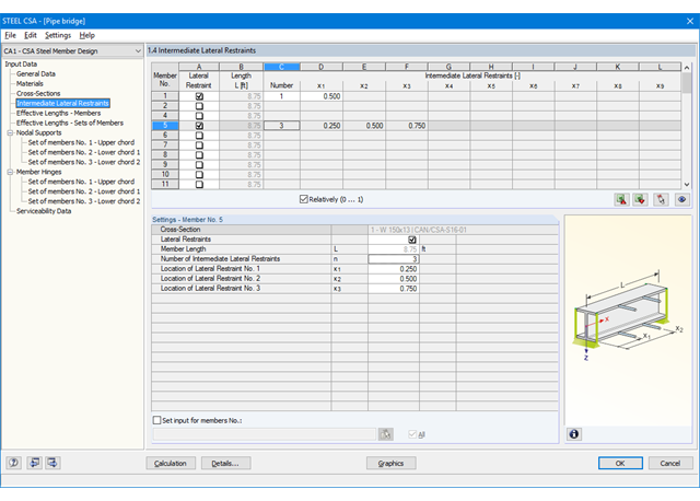
- Optional application of discrete lateral supports to beams and continuous members
- Automatic cross-section classification
- Serviceability limit state design (deflection)
- Cross-section optimization
- A wide range of available cross-sections, such as rolled I-sections; channel sections; T-sections; angles; rectangular and circular hollow sections; round bars; symmetrical and asymmetrical, parametric I-, T-, and angle sections; double angles
- Clearly arranged input and result windows
- Detailed result documentation including references to design equations of the used standard
- Various filter and sorting options of results, including result lists by member, cross-sections, x-location, or by load case, load and result combination
- Result tables of member slenderness and governing internal forces
- Parts list with weight and solid specifications
- Seamless integration in RFEM/RSTAB
- Units metric and imperial
- Design of members and sets of members for tension, compression, bending, shear, torsion, and combined internal forces
- Stability analysis of buckling and lateral-torsional buckling
- Automatic determination of effective radius of gyration by special integrated FEA software (eigenvalue analysis) for general loading and support conditions
- Alternative analytical calculation of effective radius of gyration for standard situations
- Optional application of discrete lateral supports to beams
- Definition of nodal supports for sets of members
- Serviceability limit state design (deflection)
- Cross-section optimization
- A wide range of available cross-sections, such as rolled I-sections, channel sections, T-sections, angles, rectangular and circular hollow sections, round bars, and many others.
- Detailed result documentation including references to design equations of the used standard
- Various filter and sorting options of results, including result lists by member, cross-sections, and x-location, or by load case, load and result combination
- Result table of member slenderness and governing internal forces
- Metric and imperial units
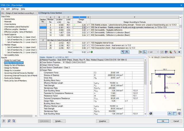
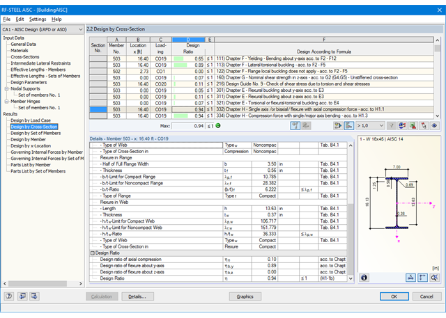
The first result window shows the maximum design ratios including the corresponding design of each designed load case (load combination / result combination).
The other result windows list all detailed results sorted by specific subject in extendable tree menus. All intermediate results along a member can be displayed at any location. In this way, you can easily retrace how the module has performed the individual designs.
The complete module data are part of the RFEM/RSTAB printout report. You can select the report contents and extent specifically for the individual designs.
It is necessary to enter material, load, and combination data in RFEM/RSTAB in compliance with the design concept specified by CSA S16. The RFEM/RSTAB material library already contains materials relevant for the Canadian standard.
RFEM/RSTAB automatically creates the corresponding load combinations according to the Canadian standard. However, you can also create all the combinations manually in RFEM/RSTAB. The RF-/STEEL CSA add-on module requires members and sets of members, as well as load cases, load combinations, and result combinations to be designed.
In the subsequent input windows, you can adjust preset definitions of lateral intermediate supports and effective lengths. In the case of continuous members, it is possible to define individual support conditions and eccentricities of each intermediate node of single members. A special FEA tool then determines the critical loads and moments required for the stability analysis in these situations.
Dlubal_KohlA.png?mw=640&hash=8712eab8f6f7bd193aba63a130c51e23e354de95)
- Consideration of the self-weight of a tower, including equipment
- Wind load distribution to exposed and shaded tower faces, or user-defined distribution
- Determination of wind loads applied to tower and equipment, especially for structures prone to vibration (gust factor)
- Assignment of surface and concentrated loads to platforms
- Optional reduction of total wind load on selected objects
- Determination of ice loads for icing classes G and R with preset ice thickness and ice flag lengths of frost
- Generation of variable load cases with surface and maintenance loads
The first result window shows the maximum design ratios with the corresponding design of each designed load case, load combination, or result combination.
The other result windows list all detailed results sorted by specific subject in extendable tree menus. All intermediate results along the members can be displayed at any location. In this way, you can easily retrace how the module has performed the individual designs.
The complete module data are part of the RFEM/RSTAB printout report. You can select the report contents and extent specifically for the individual designs.
- Applicable for members defined as sets of members
- Separate solver that considers 7 deformation directions (ux, uy, uz, φx, φy, φz, ω) or 8 internal forces (N, Vu, Vv, Mt,pri, Mt,sec, Mu, Mv, Mω)
- Nonlinear design according to second-order analysis
- Input of imperfections
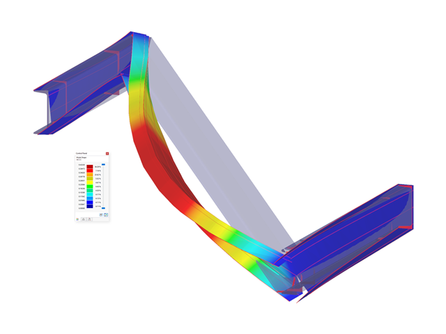
- Calculation of critical load factors and buckling mode shapes as well as the visualization of them (incl. warping)
- Integration into member design in the RF-/STEEL AISC and RF‑/STEEL EC3 add‑on modules
- Available for all thin‑walled steel cross‑sections
The first results window shows the maximum design ratios with the corresponding design of each designed load case, load combination, or result combination.
The other result windows list all detailed results sorted by specific subject in extendable tree menus. All intermediate results along a member can be displayed at any location. In this way, you can easily retrace how the module has performed the individual designs.
The complete data from the module are part of the RFEM/RSTAB printout report.
Was your design successful? Very good, now comes the relaxed part. Because the program gives you the performed design checks in a table. You can display all result details in detail here. The clearly presented design formulas ensure that you will be able to understand the results without any problems. There is no black-box effect with Dlubal Software.
The design checks are carried out at all governing locations of the members and displayed graphically as a result diagram. You can find more detailed graphics in the result output. This includes the stress distribution on the cross-section or the governing mode shape, for example.
All input and result data are part of the RFEM/RSTAB printout report. You can select the report contents and extent specifically for the individual design checks.

For the design according to Eurocode 9, you find the parameters of the National Annexes (NA) integrated for the following countries:
-
 DIN EN 1999-1-1/NA:2021-03 (Germany)
 -
 ÖNORM EN 1999-1-1/NA:2017-11 (Austria)
 -
 SN EN 1999-1-1/NA:2015-01 (Switzerland)
 -
 BDS EN 1999-1-1/NA:2014-05 (Bulgaria)
 -
 BS EN 1999-1-1/NA:2014-03 (United Kingdom)
 -
 CEN 1999-1-1/2013-12 (European Union)
 -
 CYS EN 1999-1-1/NA:2019-08 (Cyprus)
 -
 CZE EN 1999-1-1/NA:2015-09 (Czech Republic)
 -
 DS EN 1999-1-1/NA:2019-09 (Denmark)
 -
 ELOT EN 1999-1-1/NA:2013-12 (Greece)
 -
 EVS EN 1999-1-1/NA:2014-01 (Estonia)
 -
 HRN EN 1999-1-1/NA:2015-02 (Croatia)
 -
 I S. EN 1999-1-1/NA:2015-01 (Ireland)
 -
 ILNAS EN 1999-1-1/NA:2013-12 (Luxembourg)
 -
 IST EN 1999-1-1/NA:2014-03 (Iceland)
 -
 LST EN 1999-1-1/NA:2014-03 (Lithuania)
 -
 LVS EN 1999-1-1/NA:2015-01 (Latvia)
 -
 MSZ EN 1999-1-1/NA:2014-04 (Hungary)
 -
 NBN EN 1999-1-1/NA:2014-01 (Belgium)
 -
 NEN EN 1999-1-1/NA:2014-01 (Netherlands)
 -
 NF EN 1999-1-1/NA:2016-07 (France)
 -
 NP EN 1999-1-1/NA:2014-11 (Portugal)
 -
 NS EN 1999-1-1/NA:2014-04 (Norway)
 -
 PN EN 1999-1-1/NA:2014-05 (Poland)
 -
 SFS EN 1999-1-1/NA:2018-01 (Finland)
 -
 SIST EN 1999-1-1/NA:2014-05 (Slovenia)
 -
 SR EN 1999-1-1/NA:2015-01 (Romania)
 -
 SS EN 1999-1-1/NA:2013-12 (Sweden)
 -
 STN EN 1999-1-1/NA:2014-05 (Slovakia)
 -
 TKP EN 1999-1-1/NA:2010-01 (Belarus)
 -
 UNE EN 1999-1-1/NA:2014-01 (Spain)
 -
 UNI EN 1999-1-1/NA:2014-02 (Italy)