
The Steel Joints add-on provides you with the option to connect circular hollow sections using welds.
It is possible to connect the circular sections to each other or to planar structural components. The fillets of standard and thin-walled sections can also be connected with a weld.
Go to Explanatory Video
In the Steel Joints add-on, you can classify the joint stiffness.
In addition to the initial stiffness, the table also shows the limit values for hinged and rigid connections for the selected internal forces N, My, and/or Mz. The resulting classification is then displayed in tables as "hinged", "semi-rigid", or "rigid".
Go to Explanatory Video
In the "Steel Joints" add-on, you can consider preloaded bolts in all components during the calculation. You can easily activate the preloading using the check box in the bolt parameters, and it has an impact on the stress-strain analysis as well as the stiffness analysis.
Preloaded bolts are special bolts used in steel structures to generate a high clamping force between the connected structural components. This clamping force causes friction between the structural components, which allows for the transfer of forces.
Functionality
Preloaded bolts are tightened with a certain torque, causing them to stretch and generate a tensile force. This tensile force is transferred to the connected components and leads to a high clamping force. The clamping force prevents the connection from loosening and ensures safe force transmission.
Advantages
- High load-bearing capacity: Preloaded bolts can transfer large forces.
- Low deformation: They minimize the deformation of the connection.
- Fatigue strength: They are resistant to fatigue.
- Easy assembly: They are relatively easy to assemble and disassemble.
Analysis and Design
The calculation of preloaded bolts is performed in RFEM using the FE analysis model generated by the "Steel Joints" add-on. It takes into account the clamping force, friction between structural components, shear strength of bolts, and load-bearing capacity of the structural components. The design is carried out according to DIN EN 1993‑1‑8 (Eurocode 3) or the US standard ANSI/AISC 360‑16. You can save the created analysis model, including the results, and use it as an independent RFEM model.

The initial stiffness Sj,ini is a crucial parameter for evaluating whether a connection can be characterized as rigid, semi-rigid, or pinned.
In the "Steel Joints" add-on, you can calculate the initial stiffness Sj,ini according to Eurocode (EN 1993‑1‑8, Section 5.2.2) and AISC (AISC 360-16, Cl. E3.4) with regard to the internal forces N, My, and/or Mz.
The optional automatic transfer of initial stiffnesses allows for a directly transfer as member hinge stiffnesses in RFEM. The entire structure is then recalculated and the resulting internal forces are automatically adopted as loads in the analysis and design of the connection models.
This automated iteration process eliminates the need for manual export and import of data, reducing the amount of work and minimizing potential sources of error.
Explanatory Video: Calculation of Initial Stiffness Sj,ini
The design of cold-formed steel members according to the AISI S100-16 / CSA S136-16 is available in RFEM 6. Design can be accessed by selecting “AISC 360” or “CSA S16” as the standard in the Steel Design Add-on. “AISI S100” or “CSA S136” is then automatically selected for the cold-formed design.
RFEM applies the Direct Strength Method (DSM) to calculate the elastic buckling load of the member. The Direct Strength Method offers two types of solutions, numerical (Finite Strip Method) and analytical (Specification). The FSM signature curve and buckling shapes can be viewed under Sections.

In the Steel Joint add-on, you can design the connections of members with composite cross-sections. Furthermore, you can perform joint design checks for almost all thin-walled cross-sections in the RFEM library.
Go to Explanatory Video
In the Steel Joints add-on, you can design connections according to the American standard ANSI/AISC 360‑16. The following design procedures are integrated:
- Load and Resistance Factor Design (LRFD)
- Allowable Stress Design (ASD)

The new steel sections according to the latest CISC Handbook (12th edition) are available in RFEM 6. The sections are listed in the Standardized library. In the filter, select “Canada” for the region and “CISC 12” for the standard. Alternatively, the section name can be directly entered in the search box located at the bottom of the dialog box.
- Consideration of 7 local deformation directions (ux, uy, uz, φx, φy, φz, ω) or 8 internal forces (N, Vu, Vv, Mt,pri, Mt,sec, Mu, Mv, Mω) when calculating member elements
- Usable in combination with a structural analysis according to linear static, second-order, and large deformation analysis (imperfections can also be taken into account)
- In combination with the Stability Analysis add-on, allows you to determine critical load factors and mode shapes of stability problems such as torsional buckling and lateral-torsional buckling
- Consideration of end plates and transverse stiffeners as warping springs when calculating I-sections with automatic determination and graphical display of the warping spring stiffness
- Graphical display of the cross-section warping of members in the deformation
- Full integration with RFEM and RSTAB

You can perform the calculation of the warping torsion on the entire system. Thus, you consider the additional 7th degree of freedom in the member calculation. The stiffnesses of the connected structural elements are automatically taken into account. It means, you don't need to define equivalent spring stiffnesses or support conditions for a detached system.
You can then use the internal forces from the calculation with warping torsion in the add-ons for the design. Consider the warping bimoment and the secondary torsional moment, depending on the material and the selected standard. A typical application is the stability analysis according to the second-order theory with imperfections in steel structures.
Did you know that The application is not limited to thin-walled steel cross-sections. Thus, it is possible for you, for example, to perform the calculation of the ideal overturning moment of beams with solid timber cross-sections.

- You can activate or deactivate the use of torsional warping in the Add-ons tab of the model's Base Data.
- After activating the add-on, the user interface in RFEM is extended by some new entries in the navigator, tables, and dialog boxes.

Wind loads are also not a problem in your design. You can automatically generate wind loads as member loads or area loads (RFEM) on the following structural components:
- Vertical walls
- Flat roofs
- Monopitch roofs
- Duopitch/troughed roofs
- Vertical walls with duopitch roof
- Vertical walls with flat/monopitch roof
The following standards are available to you:
-
 EN 1991-1-4 (including National Annexes)
 -
 ASCE 7
 -
 CTE DB-SE-AE
 -
 GB 50009
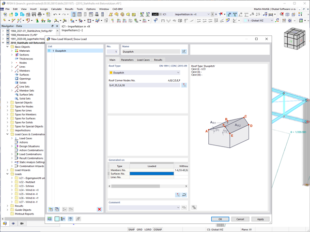
Do your structures also have to withstand snowfall? Use the Snow Load Wizard to generate snow loads as member loads or surface loads.
The following standards are available:
-
EN 1991-1-3 (incl. National Annexes)
-
ASCE 7
-
 NBC
NBC -
 SIA 261
 -
CTE DB-SE-AE
-
GB 50009
-
 IS 875
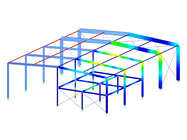
Due to the integrated RF-/STEEL Warping Torsion module extension, it is possible to perform the design according to Design Guide 9 in RF-/STEEL AISC.
The calculation is performed with 7 degrees of freedom according to the warping torsion theory and enables a realistic stability design, including consideration of torsion.
The determination of the critical buckling moment is carried out in RF-/STEEL AISC by using the eigenvalue solver which allows an exact determination of the critical buckling load.
The eigenvalue solver shows a display window of the eigenvalue graphics, which enables checking of the boundary conditions.
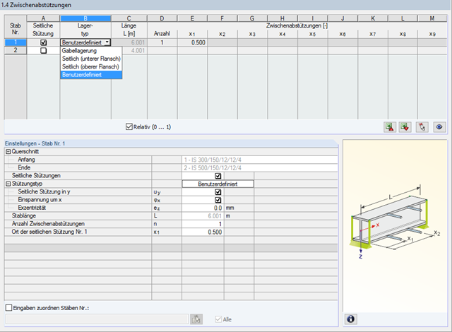
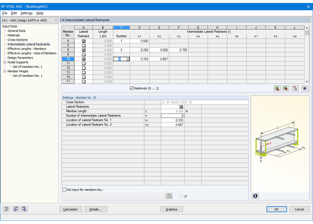
In STEEL AISC, it is possible to consider lateral intermediate supports at any location. For example, it is possible to stabilize only the upper flange.
Furthermore, user-defined lateral intermediate supports can be assigned; for example, single rotational springs and translational springs at any location at the cross-section.
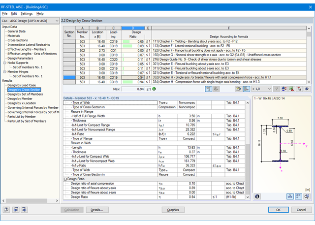
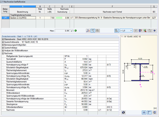
The first result window shows the maximum design ratios with the corresponding design of each designed load case, load combination, or result combination.
The other result windows list all detailed results sorted by specific subject in extendable tree menus. All intermediate results along the members can be displayed at any location. In this way, you can easily retrace how the module has performed the individual designs.
The complete module data are part of the RFEM/RSTAB printout report. You can select the report contents and extent specifically for the individual designs.
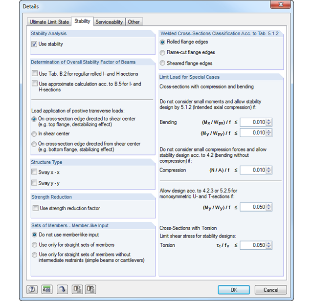
First, it is necessary to decide whether to perform design according to ASD or LRFD. Then, you can enter the load cases, load combinations, and result combinations to be designed. Load combinations according to ASCE 7 can be generated either manually or automatically in RFEM/RSTAB.
In the next steps, you can adjust presettings of lateral intermediate supports, effective lengths, and other standard-specific design parameters, such as the modification factor Cb for lateral-torsional buckling or the shear lag factor. In the case of continuous members, it is possible to define individual support conditions and eccentricities of each intermediate node of single members. A special FEA tool determines critical loads and moments required for the stability analysis.
In connection with RFEM/RSTAB, it is possible to apply the Direct Analysis Method taking into account the influence of the general calculation according to the second-order analysis. In this way, you avoid using special enlargement factors.
- Design of members and sets of members for tension, compression, bending, shear, combined internal forces, and torsion
- Stability analysis of buckling and lateral-torsional buckling
- Automatic determination of critical buckling loads and critical buckling moments for general load applications and support conditions by means of a special FEA program (eigenvalue analysis) integrated in the module
- Alternative analytical calculation of the critical buckling moment for standard situations
- Optional application of discrete lateral supports to beams and continuous members
- Automatic cross-section classification (compact, noncompact, and slender)
- Serviceability limit state design (deflection)
- Cross-section optimization
- A wide range of available cross-sections, such as rolled I-sections; channel sections; T-sections; angles; rectangular and circular hollow sections; round bars; symmetrical and asymmetrical, parametric I-, T-, and angle sections; double angles
- Clearly arranged input and result windows
- Detailed result documentation including references to design equations of the used standard
- Various filter and sorting options of results, including result lists by member, cross-sections, and x-location, or by load case, load combination, and result combination
- Result table of member slenderness and governing internal forces
- Parts list with weight and solid specifications
- Seamless integration in RFEM/RSTAB
- Metric and imperial units
- Applicable for members defined as sets of members
- Separate solver that considers 7 deformation directions (ux, uy, uz, φx, φy, φz, ω) or 8 internal forces (N, Vu, Vv, Mt,pri, Mt,sec, Mu, Mv, Mω)
- Nonlinear design according to second-order analysis
- Input of imperfections
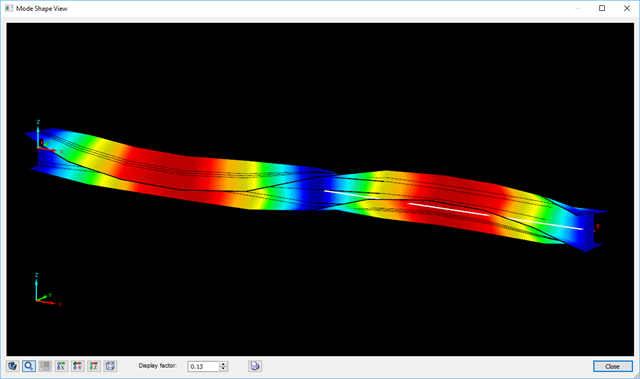
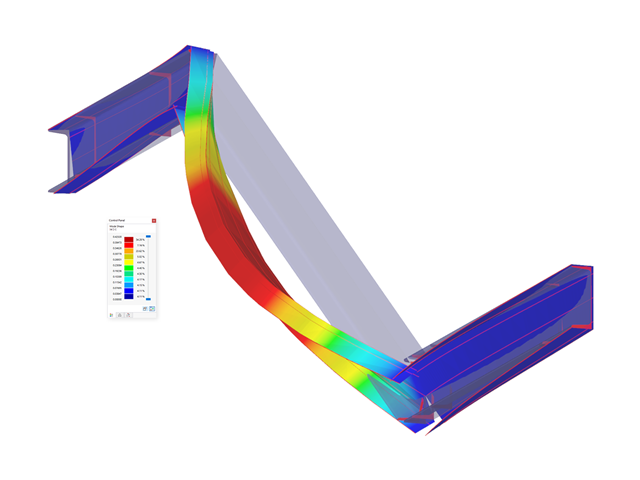
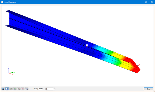
- Calculation of critical load factors and buckling mode shapes as well as the visualization of them (incl. warping)
- Integration into member design in the RF-/STEEL AISC and RF‑/STEEL EC3 add‑on modules
- Available for all thin‑walled steel cross‑sections
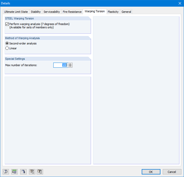
Since RF-/STEEL Warping Torsion is fully integrated in RF-/STEEL AISC and RF‑/STEEL EC3, the data are entered in the same way as for the usual design in these modules. It is only necessary to select the option "Perform warping analysis" in the Details dialog box, tab Warping Torsion (see the figure on the right). You can also define the maximum number of iterations in this dialog box.
The warping torsion analysis is performed for sets of members in RF-/STEEL AISC and RF‑/STEEL EC3. You can define boundary conditions such as nodal supports or member end releases for them.
It is also possible to specify imperfections for the nonlinear calculation.
The results of warping torsion analysis are displayed in RF-/STEEL AISC and RF-/STEEL EC3 in the usual way. Among other results, the corresponding result windows include the critical warping and torsional values, internal forces, and design summary.
The graphical display of mode shapes (incl. warping) enables a realistic assessment of buckling behavior.
The first window shows the maximum design ratios including the corresponding design of each designed load case, load combination, or result combination.
The other result windows list all detailed results sorted by specific subject in extendable tree menus. All intermediate results along the members can be displayed at any location. In this way, you can easily retrace how the module has performed the individual designs.
The complete module data are part of the RFEM/RSTAB printout report. You can select the report contents and extent specifically for the individual designs.
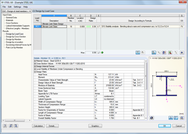
It is necessary to enter material, load, and combination data in RFEM/RSTAB in compliance with the design concept specified by GB 50017. The RFEM/RSTAB material library already contains the relevant materials.
The RF-/STEEL GB add-on module requires members and sets of members, as well as load cases, load combinations, and result combinations to be designed.
In the subsequent input windows, you can adjust preset definitions of lateral intermediate supports and effective lengths. This setting is then used by the program to determine the critical loads and moments required for the stability analysis in these situations.
- Design of tension, compression, bending, shear, and combined internal forces
- Stability analysis for flexural buckling and lateral-torsional buckling
- Automatic determination of critical buckling loads and overall stability factors for lateral-torsional buckling according to Annex B
- Optional application of discrete lateral supports to beams
- Automatic local stability analysis and check of plastic design criteria of a cross-section
- Deformation analysis (serviceability)
- Cross-section optimization
- Wide range of cross-sections available, such as rolled I-sections, channel sections, rectangular hollow sections, angles, T-sections. Welded sections: I-shaped (symmetrical and asymmetrical about major axis), channel sections (symmetrical about major axis), rectangular hollow sections (symmetrical and asymmetrical about major axis), angles, round pipes, and round bars
- Clearly arranged result tables
- Detailed result documentation including references to design equations of the used standard
- Various filter and sorting options of results, including result lists by member, cross-sections, x-location, or by load case, load and result combination
- Result table of member slenderness and governing internal forces
- Parts list with weight and solid specifications
- Seamless integration in RFEM/RSTAB
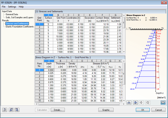
The calculated stresses and settlements are displayed in result windows. In addition, it is possible to evaluate the results graphically. The graphic displays the position and the layer arrangement of the soil samples to clarify the results.
The final result window shows the elastic foundation coefficients. Graphical evaluation is possible as well.
Elastic foundation coefficients are calculated according to the non-linear iterative method. The module determines elastic foundation coefficients for each individual element. They are dependent on the deformation.
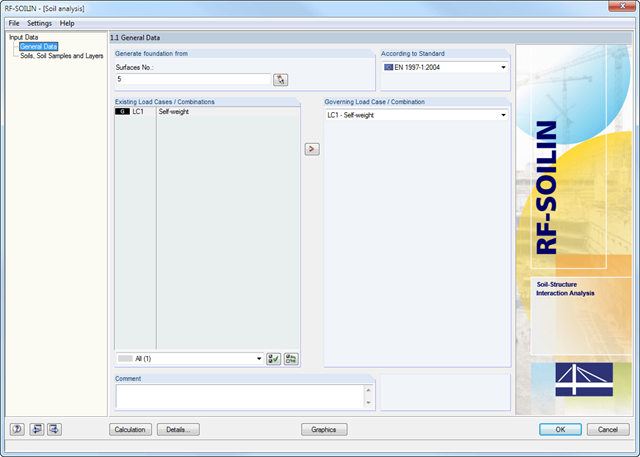
The definition of soil layers is performed in a clearly arranged input window. An extensible library facilitates the selection of soil properties.
The elasticity can be defined either by the stiffness modulus or the modulus of elasticity and the Poisson's ratio. It is possible to define any number of soil layers. You can assign the layers to the building graphically or by entering the relevant coordinates.
.png?mw=640&hash=34966a7f3c34f6b7bb83003f1c13cb57a2f0cabb)
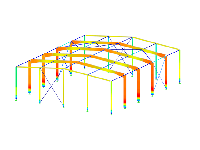
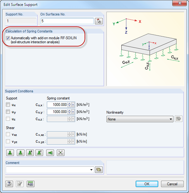
- Realistic representation of interaction between a building and soil
- Extensible library of soil properties
- Consideration of several soil samples (probes) at different locations, even outside the building
- Consideration of groundwater level as well as side effects due to excavation and lowest soil layer being solid
- Calculation of elastic foundation coefficients
- Determination and graphical display of stress diagrams and settlements in grid points
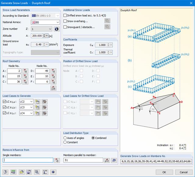
Snow loads can be generated as member loads on flat/monopitch roofs and duopitch roofs.
Additional snow loads such as drifted snow loads, snow overhangs, and snow guards can be taken into account as well.
The following standards are available:
-
EN 1991-1-3 (incl. National Annexes)
-
 DIN 1055-5
 -
CTE DB-SE-AE
-
ASCE/SEI 7-16