The material library already includes Swiss types of concrete and reinforcing steel available for design. However, you can always define other materials for the design according to SIA 262. The program performs the ultimate and the serviceability limit state design.
The crack width analysis can be performed using the design of Sigmas,adm, rebar spacing sL, or a direct calculation of crack widths according to the technical documentation D0182. Depending on the selected concrete type, the program determines the limit value Sigmas,adm according to D0182, Eq. 10.13; the upper limit is set by the design criterion fsd.
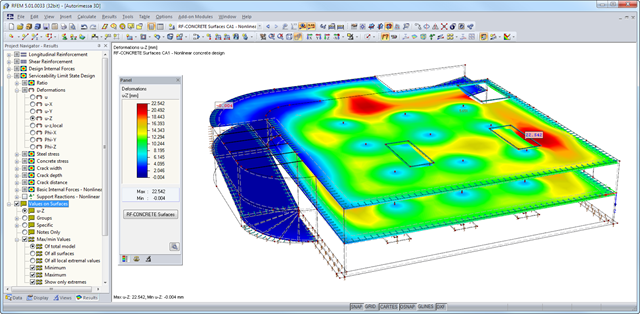
After the calculation, the module shows clearly arranged tables listing the results of the nonlinear calculation. All intermediate values are included in a comprehensible manner. Graphical representation of design ratios, deformations, concrete and reinforcing steel stresses, crack widths, crack depths, and crack spacing in RFEM facilitates a quick overview of critical or cracked areas.
Error messages or remarks concerning the calculation help you find design problems. Since the design results are displayed by surface or by point including all intermediate results, you can retrace all details of the calculation.
Due to the optional export of input or result tables to MS Excel, the data remain available for further use in other programs. The complete integration of results in the RFEM printout report guarantees verifiable structural design.
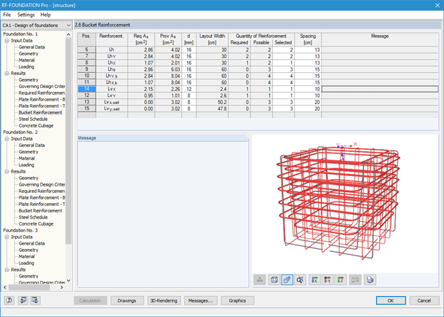
The program creates a reinforcement proposal for the top and the bottom plate reinforcement. The program searches automatically for the most favorable reinforcement combination, with a mat and added rebars. If required, the rebars are distributed across two reinforcement areas by curtailment. It is possible to modify the reinforcement proposal individually by:
- Application of another mat type
- Individual control of diameter and spacing of added rebars
- Free selection of reinforcement area widths
- Individual curtailment of reinforcements
You can display the foundation in excellent rendering quality, including reinforcement. In the rendering, as well as in up to seven different dimensioned reinforcement drawings ready for construction, the module provides a solution proposal for bucket design. It is possible to modify the number, position, diameter, and spacing of used rebars here as well. You can also determine the shape of the applied links.
The dimensions of the foundation plate and bucket can be determined by the add-on module, or can be user-defined. Clearly arranged windows display the results of each performed design, including all intermediate values. They are covered in a reduced printout report providing a verifiable structural analysis.
- Iterative nonlinear calculation of deformations for beam and plate structures consisting of reinforced concrete by determining the respective element stiffness subjected to the defined loads
- Deformation analyses of cracked reinforced concrete surfaces (state II)
- General nonlinear stability analysis of compression members made of reinforced concrete; for example, according to EN 1992-1-1, 5.8.6
- Tension stiffening of concrete applied between cracks
- Numerous National Annexes available for the design according to Eurocode 2 (EN 1992-1-1:2004 + A1:2014, see EC2 for RFEM)
- Optional consideration of long-term influences such as creep or shrinkage
- Nonlinear calculation of stresses in reinforcing steel and concrete
- Nonlinear calculation of crack widths
- Flexibility due to detailed setting options for basis and extent of calculations
- Graphical representation of results integrated in RFEM; for example, deformation or sag of a flat slab made of reinforced concrete
- Numerical results clearly arranged in tables and graphical display of the results in the model
- Complete integration of results in the RFEM printout report
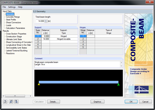
- Single-span and continuous beams with definable boundary conditions
- Automatic determination of effective cross-sections
- Free arrangement of construction supports for construction stage
- Freely definable concentrated, distributed, and trapezoidal loads as fixed loads with specification of concrete age during loading
- Freely definable construction loads as well as moving construction loads
- Automatic load combination
- Calculation of cross-section properties according to Method 1 or 2
- Calculation of elastic internal forces with RSTAB
- Redistribution of Moments
- Design of bending and shear force resistance with interaction
- Determination of required shear connectors and their distribution
- Design of longitudinal shear force resistance
- Results of governing support reactions for construction and composite stage, including loads of construction supports
- Lateral-torsional buckling analysis
- Analysis for limitation of crack widths
- Design of natural frequency
First, it is necessary to select a tower type and the relevant materials and cross-sections. The tower geometry is defined by individual tower segments. Slopes can be defined via widths or relatively by geometry modification.
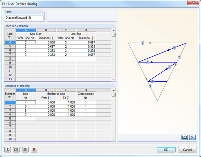
After entering the tower legs, you can specify various stiffening of the lattice tower. It is possible to enter detailed specifications of horizontal girts, inner bracing, and vertical bracing of a tower with unequal sides. An extensive library including parametrized bracing types facilitates the input.
In addition, there is an interactive graphic in all input windows.
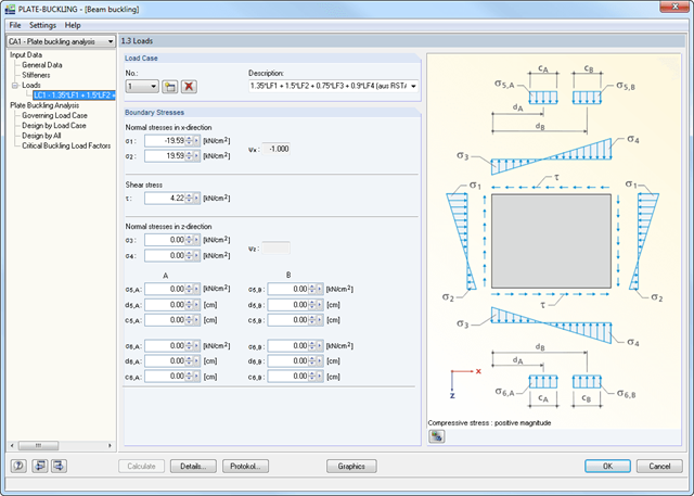
Initially, it is necessary to define material data, panel dimensions, and boundary conditions (hinged, built-in, unsupported, hinged-elastic). It is possible to transfer the data from RFEM/RSTAB. Then, boundary stresses can be either defined for each load case manually or imported from RFEM/RSTAB.
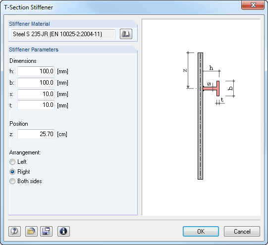
Stiffeners are modeled as spatially effective surface elements that are eccentrically connected to the plate. Therefore, it is not necessary to consider the stiffener eccentricities by effective widths. The bending, shear, strain, and St. Venant stiffness of stiffeners as well as the Bredt stiffness of closed stiffeners is determined automatically in a 3D model.
RF-CONCRETE Surfaces:
The nonlinear deformation analysis is performed by an iterative process considering the stiffness in cracked and non-cracked sections. The nonlinear reinforced concrete modeling requires definition of material properties varying across the surface thickness. Therefore, a finite element is divided into a certain number of steel and concrete layers in order to determine the cross-section depth.
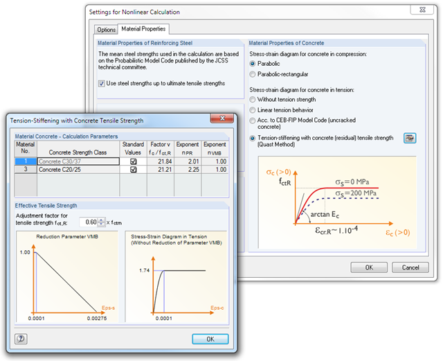
The mean steel strengths used in the calculation are based on the 'Probabilistic Model Code' published by the JCSS technical committee. It is up to the user whether the steel strength is applied up to the ultimate tensile strength (increasing branch in the plastic area). Regarding material properties, it is possible to control the stress-strain diagram of the compressive and tensile strength. For the concrete compressive strength, you can select a parabolic or a parabolic-rectangular stress-strain diagram. On the tension side of the concrete, it is possible to deactivate the tensile strength as well as to apply a linear-elastic diagram, a diagram according to the CEB-FIB model code 90:1993, and concrete residual tensile strength considering the tension stiffening between the cracks.
Furthermore, you can specify which result values should be displayed after the nonlinear calculation at the serviceability limit state:
- Deformations (global, local based on non-/deformed system)
- Crack widths, depths, and spacing of the top and bottom sides in principal directions I and II
- Stresses of the concrete (stress and strain in principal direction I and II) and of the reinforcement (strain, area, profile, cover, and direction in each reinforcement direction)
RF-CONCRETE Members:
The nonlinear deformation analysis of beam structures is performed by an iterative process considering the stiffness in cracked and non-cracked sections. The material properties of concrete and reinforcing steel used in the nonlinear calculation are selected according to a limit state. The contribution of the concrete tensile strength between the cracks (tension stiffening) can be applied either by means of a modified stress-strain diagram of the reinforcing steel, or by applying a residual concrete tensile strength.
- For the design according to Eurocode 3, the following National Annexes are available:
-
 DIN EN 1993-1-5/NA:2010-12 (Germany)
 -
 SFS EN 1993-1-5/NA:2006 (Finland)
 -
 NBN EN 1993-1-5/NA:2011-03 (Belgium)
 -
 UNI EN 1993-1-5/NA:2011-02 (Italy)
 -
 NEN EN 1993-1-5/NA:2011-04 (Netherlands)
 -
 NS EN 1993-1-5/NA:2009-06 (Norway)
 -
 CSN EN 1993-1-5/NA:2008-07 (Czech Republic)
 -
 CYS EN 1993-1-5/NA:2009-03 (Cyprus)
-
- In addition to the National Annexes listed above, you can also define a specific NA, applying user-defined limit values and parameters.
- Import of all relevant internal forces from RFEM/RSTAB by selecting numbers of members and buckling panels with determination of governing boundary stresses
- Summary of stresses in load cases with determination of governing load
- Different materials for stiffener and plate possible
- Import of stiffeners from an extensive library (flat plate and bulb flat steel, angle, T-section, channel, and trapezoidal sheeting)
- Determination of effective widths according to EN 1993-1-5 (Table 4.1 or 4.2) or DIN 18800, Part 3, Eq. (4)
- Optional calculation of critical buckling stresses according to analytical formulas of annexes A.1, A.2, and A.3 of EC 3, or by means of FEA calculation
- Designs (stress, deformation, torsional buckling) of longitudinal and transverse stiffeners
- Optional consideration of buckling effects according to DIN 18800, Part 3, Eq. (13)
- Photo-realistic representation (3D rendering) of buckling panel, including stiffeners, stress conditions, and buckling modes with animation
- Documentation of all input data and results in a verifiable printout report
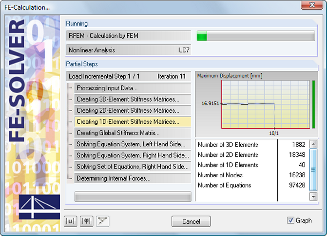
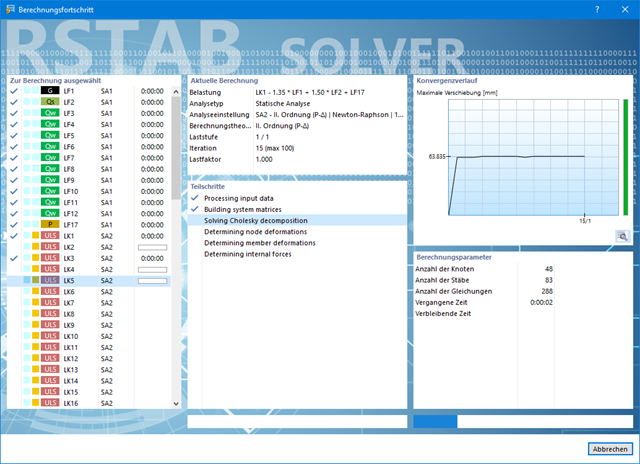
The equation solver includes an optimized FE mesh generator and supports the latest multi-core processor and 64-bit technology. It enables parallel calculations of linear load cases and load combinations using several processors without additional demands on the RAM: The stiffness matrix only has to be created once. The 64-bit technology and the enhanced RAM options allow for calculation of complex structural systems using the fast and direct equation solver.
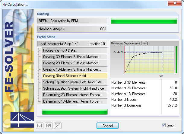
The development of the deformation is displayed in a diagram during the calculation. This way, you can easily evaluate the convergence behavior.
When determining internal forces, you can choose between calculation method 1 (uncracked over entire beam length) and calculation method 2 (crack formation over internal columns).
In both cases, it is possible to consider a constant effective width of the concrete slab over the entire span according to ENV 1994-1-1, 4.2.2.1 (1) and a redistribution of the moments. Internal forces for the design of shear connectors can only be determined by the elastic calculation of internal forces using the RSTAB analysis core (no RSTAB license is required).
The calculation performs fully automatic determination of the effective cross-section properties at the respective points of time, considering creep and shrinkage. In the RSTAB user interface, the structural models are created as a member structure, including all boundary conditions and loading. This way, reliable calculation of the internal forces with the effective cross-section properties is ensured.
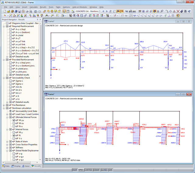
After the calculation, the module shows clearly arranged tables listing the required reinforcement and the results of the serviceability limit state design. All intermediate values are included in a comprehensible manner. In addition to the tables, current stresses and strains in a cross‑section are represented graphically.
The reinforcement proposals of the longitudinal and the shear reinforcement, including sketches, are documented in accordance with current practice. It is possible to edit the reinforcement proposal and to adjust, for example, the number of members and the anchorage. The modifications will be updated automatically.
A concrete cross‑section, including reinforcement, can be visualized in a 3D rendering. This way, the program provides an optimal documentation option to create reinforcement drawings, including steel schedule.
Crack width analyzes are performed using the selected reinforcement of internal forces in the serviceability limit state. The result output covers steel stresses, the minimum reinforcement, limit diameters, and the maximum bar spacing, as well as crack spacing and the maximum crack widths.
As a result of the nonlinear calculation, there are the ultimate limit states of the cross‑section with defined reinforcement (determined linear elastically) as well as effective deflections of the member considering stiffness in cracked state.
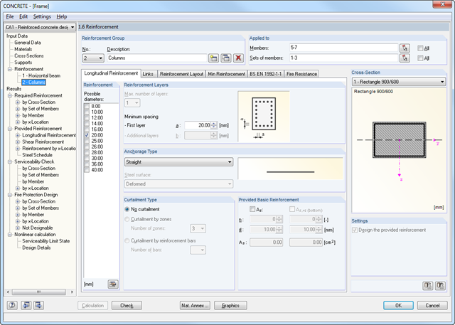
After opening the program, you can define the standard and method according to which the design is performed. The ultimate and serviceability limit states can be designed according to the linear and nonlinear calculation methods. Load cases, load combinations or result combinations are then assigned to different calculation types. In other input windows, you can define materials and cross‑sections. In addition, it is possible to assign parameters for creep and shrinkage. Creep and shrinkage coefficients are directly adjusted, depending on the age of the concrete.
Support geometry is determined by means of design‑relevant data such as support widths and types (direct, monolithic, end, or intermediate support) and redistribution of moments as well as shear force and moment reduction. CONCRETE recognizes the support types from the RSTAB model automatically.
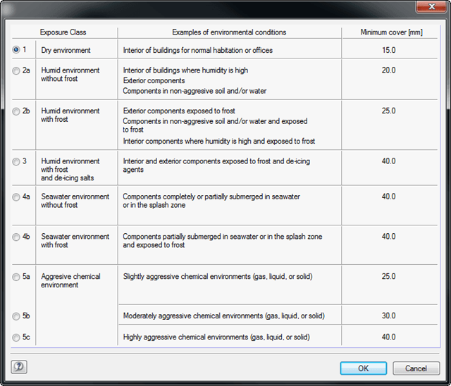
A segmented window includes the specific reinforcement data such as diameters, the concrete cover and curtailment type of reinforcements, number of layers, cutting ability of links, and the anchorage type. In the case of the fire resistance design, it is necessary to define the fire resistance class, the fire‑related material properties, and the cross-section side exposed to fire. Members and sets of members can be summarized in special 'reinforcement groups', each with different design parameters.
You can adjust the limit value of the maximum crack width in the case of crack width analysis. The geometry of tapers is to be determined additionally for the reinforcement.
RF-CONCRETE Surfaces
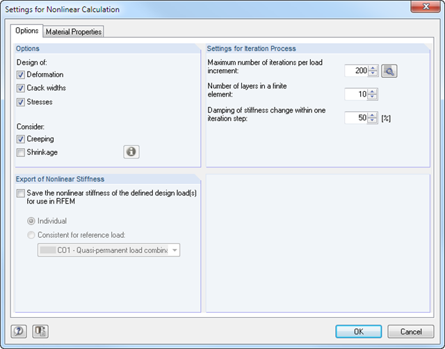
The nonlinear calculation is activated by selecting the design method of the serviceability limit state. You can individually select the analyses to be performed as well as the stress-strain diagrams for concrete and reinforcing steel. The iteration process can be influenced by these control parameters: convergence accuracy, maximum number of iterations, arrangement of layers over cross-section depth, and damping factor.
You can set the limit values in the serviceability limit state individually for each surface or surface group. Allowable limit values are defined by the maximum deformation, the maximum stresses, or the maximum crack widths. The definition of the maximum deformation requires additional specification as to whether the non-deformed or the deformed system should be used for the design.
RF-CONCRETE Members
The nonlinear calculation can be applied to the ultimate and the serviceability limit state designs. In addition, you can specify the concrete tensile strength or the tension stiffening between the cracks. The iteration process can be influenced by these control parameters: convergence accuracy, maximum number of iterations, and damping factor.

SHAPE-THIN calculates all relevant cross‑section properties, including plastic limit internal forces. Overlapping areas are set close to reality. If cross-sections consist of different materials, SHAPE‑THIN determines the effective cross‑section properties with respect to the reference material.
In addition to the elastic stress analysis, you can perform the plastic design including interaction of internal forces for any cross‑section shape. The plastic interaction design is carried out according to the Simplex Method. You can select the yield hypothesis according to Tresca or von Mises.
SHAPE-THIN performs a cross-section classification according to EN 1993-1-1 and EN 1999-1-1. For steel cross-sections of cross-section class 4, the program determines effective widths for unstiffened or stiffened buckling panels according to EN 1993-1-1 and EN 1993-1-5. For aluminum cross-sections of cross-section class 4, the program calculates effective thicknesses according to EN 1999-1-1.
Optionally, SHAPE‑THIN checks the limit c/t-values in compliance with the design methods el‑el, el‑pl, or pl‑pl according to DIN 18800. The c/t-zones of elements connected in the same direction are recognized automatically.

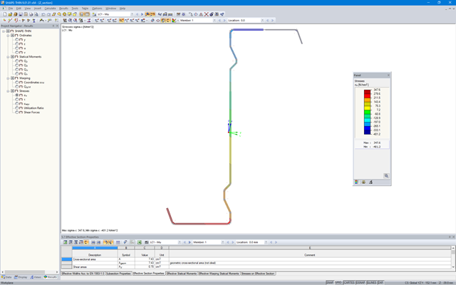
SHAPE-THIN determines the section properties and stresses of any open, closed, built-up, or non-connected cross-sections.
- Section Properties
- Cross-sectional area A
- Shear areas Ay, Az, Au, and Av
- Centroid position yS, zS
- moments of area 2 degrees Iy, Iz, Iyz, Iu, Iv, Ip, Ip,M
- Radii of gyration iy, iz, iyz, iu, iv, ip, ip,M
- Inclination of principal axes α
- Cross-section weight G
- Cross-section perimeter U
- torsional constants of area degrees IT, IT,St.Venant, IT,Bredt, IT,s
- Location of the shear center yM, zM
- Warping constants Iω,S, Iω,M or Iω,D for lateral restraint
- Max/min section moduli Sy, Sz, Su, Sv, Sω,M with locations
- Section ranges ru, rv, rM,u, rM,v
- Reduction factor λM
- Plastic Cross-Section Properties
- Axial force Npl,d
- Shear forces Vpl,y,d, Vpl,z,d, Vpl,u,d, Vpl,v,d
- Bending moments Mpl,y,d, Mpl,z,d, Mpl,u,d, Mpl,v,d
- Section moduli Zy, Zz, Zu, Zv
- Shear areas Apl,y, Apl,z, Apl,u, Apl,v
- Position of area bisecting axes fu, fv,
- Display of the inertia ellipse
- First moments of area Qu, Qv, Qy, Qz with location of maxima and specification of shear flow
- Warping coordinates ωM
- moments of area (warping areas) Sω,M
- Cell areas Am of closed cross-sections
- Normal stresses σx due to axial force, bending moments, and warping bimoment
- Shear stresses τ from shear forces as well as primary and secondary torsional moments
- Equivalent stresses σv with customizable factor for shear stresses
- Stress ratios, related to limit stresses
- Stresses for element edges or center lines
- Weld stresses in fillet welds
- Section properties of non-connected cross-sections (cores of high-rise buildings, composite sections)
- Shear wall shear forces due to bending and torsion
- Plastic capacity design with determination of the enlargement factor αpl
- Check of the c/t-ratios following the design methods el-el, el-pl or pl-pl according to DIN 18800

- Import of materials, cross-sections, and internal forces from RFEM/RSTAB
- Steel design of thin‑walled cross‑sections according to EN 1993‑1‑1:2005 and EN 1993‑1‑5:2006
- Automatic classification of cross-sections according to EN 1993-1-1:2005 + AC:2009, Cl. 5.5.2, and EN 1993-1-5:2006, Cl. 4.4 (cross-section class 4), with optional determination of effective widths according to Annex E for stresses under fy
- Integration of parameters for the following National Annexes:
-
DIN EN 1993-1-1/NA:2015-08 (Germany)
-
 ÖNORM B 1993-1-1:2007-02 (Austria)
 -
NBN EN 1993-1-1/ANB:2010-12 (Belgium)
-
 BDS EN 1993-1-1/NA:2008 (Bulgaria)
 -
 DS/EN 1993-1-1 DK NA:2015 (Denmark)
 -
SFS EN 1993-1-1/NA:2005 (Finland)
-
 NF EN 1993-1-1/NA:2007-05 (France)
 -
 ELOT EN 1993-1-1 (Greece)
 -
UNI EN 1993-1-1/NA:2008 (Italy)
-
 LST EN 1993-1-1/NA:2009-04 (Lithuania)
 -
 UNI EN 1993-1-1/NA:2011-02 (Italy)
 -
 MS EN 1993-1-1/NA:2010 (Malaysia)
 -
NEN EN 1993-1-1/NA:2011-12 (Netherlands)
- NS EN 1993-1-1/NA:2008-02 (Norway)
-
 PN EN 1993-1-1/NA:2006-06 (Poland)
 -
 NP EN 1993-1-1/NA:2010-03 (Portugal)
 -
 SR EN 1993-1-1/NB:2008-04 (Romania)
 -
 SS EN 1993-1-1/NA:2011-04 (Sweden)
 -
 SS EN 1993-1-1/NA:2010 (Singapore)
 -
 STN EN 1993-1-1/NA:2007-12 (Slovakia)
 -
 SIST EN 1993-1-1/A101:2006-03 (Slovenia)
 -
 UNE EN 1993-1-1/NA:2013-02 (Spain)
 -
CSN EN 1993-1-1/NA:2007-05 (Czech Republic)
-
 BS EN 1993-1-1/NA:2008-12 (the United Kingdom)
 -
CYS EN 1993-1-1/NA:2009-03 (Cyprus)
- In addition to the National Annexes (NA) listed above, you can also define a specific NA, applying user‑defined limit values and parameters.
- Automatic calculation of all required factors for the design value of flexural buckling resistance Nb,Rd
- Automatic determination of the ideal elastic critical moment Mcr for each member or set of members on every x-location according to the Eigenvalue Method or by comparing moment diagrams. You only have to define the lateral intermediate supports.
- Design of tapered members, unsymmetric sections or sets of members according to the General Method as described in EN 1993-1-1, Cl. 6.3.4
- In the case of the General Method according to Cl. 6.3.4, optional application of "European lateral-torsional buckling curve" according to Naumes, Strohmann, Ungermann, Sedlacek (Stahlbau 77 [2008], pp. 748‑761)
- Rotational restraints can be taken into account (trapezoidal sheeting and purlins)
- Optional consideration of shear panels (for example, trapezoidal sheeting and bracing)
- RF-/STEEL Warping Torsion module extension (license required) for stability analysis according to the second-order analysis as stress analysis including consideration of the 7th degree of freedom (warping)
- Module extension RF-/STEEL Plasticity (license required) for plastic analysis of cross‑sections according to Partial Internal Forces Method (PIFM) and Simplex Method for general cross‑sections (in connection with the RF‑/STEEL Warping Torsion module extension, it is possible to perform the plastic design according to the second‑order analysis)
- Module extension RF-/STEEL Cold-Formed Sections (license required) for ultimate and serviceability limit state designs for cold-formed steel members according to the EN 1993-1-3 and EN 1993-1-5 standards
- ULS design: Selection of fundamental or accidental design situations for each load case, load combination, or result combination
- SLS design: Selection of characteristic, frequent, or quasi-permanent design situations for each load case, load combination, or result combination
- Tension analysis with definable net cross-section areas for member start and end
- Weld designs of welded cross-sections
- Optional calculation of warp spring for nodal support on sets of members
- Graphic of design ratios on cross-section and in RFEM/RSTAB model
- Determination of governing internal forces
- Filter options for graphical results in RFEM/RSTAB
- Representation of design ratios and cross‑section classes in the rendered view
- Color scales in result windows
- Automatic cross-section optimization
- Transfer of optimized cross-sections to RFEM/RSTAB
- Parts lists and quantity surveying
- Direct data export to MS Excel
- Verifiable printout report
- Possibility to include the temperature curve in the report

- 3D incompressible wind flow analysis with OpenFOAM® software package
- Direct model import from RFEM or RSTAB including neighboring and terrain models (3DS, IFC, STEP files)
- Model design via STL or VTP files independent of RFEM or RSTAB
- Simple model changes using Drag and Drop and graphical adjustment assistance
- Automatic corrections of the model topology with shrink wrap networks
- Option to add objects from the environment (buildings, terrain ...)
- Wind load determined over the height of the building, depending on standard-specific parameters (velocity, turbulence intensity)
- K-epsilon and K-omega turbulence models
- Automatic mesh generation adjusted to the selected depth of detail
- Parallel calculation with optimal utilization of the capacity of multicore computers
- Results in just minutes for low-resolution simulations (up to 1 million cells)
- Results within a few hours for simulations with medium/high resolution (1‑10 million cells)
- Graphical display of results on the Clipper/Slicer planes (scalar and vector fields)
- Graphical display of streamlines
- Streamline animation (optional video creation)
- Definition of point and line probes
- Display of aerodynamic pressure coefficients
- Graphical display of turbulence properties in the wind field
- Optional meshing using the boundary layer option for the area near the model surface
- Consideration of rough model surfaces possible
- Optional use of a seond-order numerical Order
- Multilingual user interface (for example, German, English, Spanish, French)
- Documentation possible in the RFEM and RSTAB printout report
SHAPE‑THIN determines the effective cross-sections according to EN 1993‑1‑3 and EN 1993‑1‑5 for cold-formed sections. You can optionally check the geometric conditions for the applicability of the standard specified in EN 1993‑1‑3, Section 5.2.
The effects of local plate buckling are considered according to the method of reduced widths, and the possible buckling of stiffeners (instability) is considered for stiffened sections according to EN 1993‑1‑3, Section 5.5.
As an option, you can perform an iterative calculation to optimize the effective cross-section.
You can display the effective cross-sections graphically.
Read more about designing cold-formed sections with SHAPE-THIN and RF-/STEEL Cold-Formed Sections in the technical article "Design of Thin-Walled, Cold-Formed C-Section According to EN 1993‑1‑3".
Design of Thin-Walled, Cold-Formed C-Section According to EN 1993-1-3 More about RF-/STEEL Cold-Formed Sections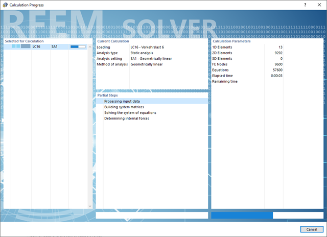
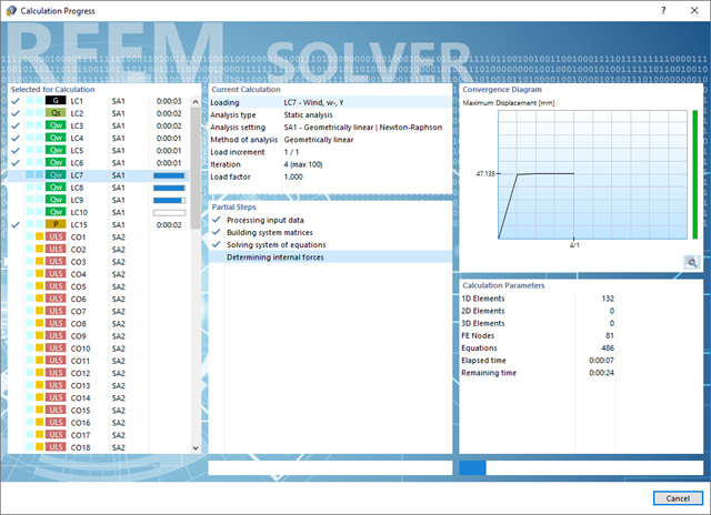
Convince yourself by the powerful calculation kernel, its optimized networking and support of multi-core processor technology. This provides you with the advantages, such as parallel calculations of linear load cases and load combinations using several processors without additional demands on the RAM. The stiffness matrix only has to be created once. Thus, you can calculate even large systems with the fast direct solver.
If you need to calculate multiple load combinations in your models, the program initiates several solvers in parallel (one per core). Each solver then calculates a load combination, which improves the core utilization.
You can systematically follow the development of the deformation displayed in a diagram during the calculation, and thus precisely evaluate the convergence behavior.
Also in this case, RSTAB will certainly convince you. With the powerful calculation kernel, its optimized networking and support of multi-core processor technology, the Dlubal structural analysis program is far ahead. This allows you to calculate more linear load cases and load combinations using several processors in parallel without using additional memory. The stiffness matrix only has to be created once. Thus, it is possible for you to calculate even large systems with the fast and direct solver.
Do you have to calculate multiple load combinations in your models? The program initiates several solvers in parallel (one per core). Each solver then calculates a load combination for you. This leads to better utilization of the cores.
You can systematically follow the development of the deformation displayed in a diagram during the calculation, and thus precisely evaluate the convergence behavior.
Do you have to calculate multiple load combinations in your models? Then several solvers (one per core) are initiated in parallel, each of which calculates a load combination. This ensures a better utilization of the cores and thus faster calculations.
Go to Explanatory Video
- Calculation of stationary incompressible turbulent wind flow using the SimpleFOAM solver from the OpenFOAM® software package
- Numerical scheme according to the first and second order
- Turbulence models RAS k-ω and RAS k-ε
- Consideration of surface roughness depending on model zones
- Model design via VTP, STL, OBJ, and IFC files
- Operation via bidirectional interface of RFEM or RSTAB for importing model geometries with standard-based wind loads and exporting wind load cases with probe-based printout report tables
- Intuitive model changes via drag & drop and graphical adjustment assistance
- Generation of a shrink-wrap mesh envelope around the model geometry
- Consideration of environmental objects (buildings, terrain, and so on)
- Height-dependent description of the wind load (wind speed and turbulence intensity)
- Automatic meshing depending on a selected depth of detail
- Consideration of layer meshes near the model surfaces
- Parallelized calculation with optimal utilization of all processor cores of a computer
- Graphical output of the surface results on the model surfaces (surface pressure, Cp coefficients)
- Graphical output of the flow field and vector results (pressure field, velocity field, turbulence – k-ω field, and turbulence – k-ε field, velocity vectors) on Clipper/Slicer planes
- Display of 3D wind flow via animated streamline graphics
- Definition of point and line probes
- Multilingual user interface (German, English, Czech, Spanish, French, Italian, Polish, Portuguese, Russian, and Chinese)
- Calculations of several models in one batch process
- Generator for creating rotated models to simulate different wind directions
- Optional interruption and continuation of the calculation
- Individual color panel per result graphic
- Display of diagrams with separate output of results on both sides of a surface
- Output of the dimensionless wall distance y+ in the mesh inspector details for the simplified model mesh
- Determination of the shear stress on the model surface from the flow around the model
- Calculation with an alternative convergence criterion (you can select between the residual types pressure or flow resistance in the simulation parameters)
.png?mw=640&hash=3c928fddb4215c3df06e0b731d5c3f2e475cd9db)
Within a member, you can define the integration width and effective slab width of T-beams (ribs) with different widths. The member is divided into segments. You can either grade or specify the transition between the different flange widths as linearly variable. Furthermore, the program allows you to consider the defined surface reinforcement as a flange reinforcement for the reinforced concrete design of a rib.