
The Concrete Design add-on provides you with the option to perform the simplified fire resistance design according to EN 1992‑1‑2 for columns (Section 5.3.2) and beams (Section 5.6).
The following design checks are available for the simplified fire resistance design:
- Columns: Minimum cross-sectional dimensions for rectangular and circular sections according to Table 5.2a as well as Equation 5.7 for calculating time of fire exposure
- Beams: Minimum dimensions and center distances according to Table 5.5 and Table 5.6
You can determine the internal forces for the fire resistance design according to two methods.
- 1 Here, the internal forces of the accidental design situation are included directly into the design.
- 2 The internal forces of the design at normal temperature are reduced by the factor Eta,fi (ηfi), then used in the fire resistance design.
Furthermore, it is possible to modify the axis distance according to Eq. 5.5.

- Analysis of time diagrams and accelerograms (acceleration-time diagrams exciting the supports of a structure)
- Combination of user-defined time diagrams with nodal, member, and surface loads, as well as free and generated loads
- Combination of several independent excitation functions
- Linear implicit Newmark analysis or modal analysis in time history
- Structural damping using Raleigh damping coefficients or Lehr's damping value
- Graphical display of results in calculation diagrams
- Result display in individual time steps or as an envelope during the entire time period
- Extensive library of seismic events (accelerograms)

In the Steel Joints add-on, you can classify the joint stiffness.
In addition to the initial stiffness, the table also shows the limit values for hinged and rigid connections for the selected internal forces N, My, and/or Mz. The resulting classification is then displayed in tables as "hinged", "semi-rigid", or "rigid".
Go to Explanatory Video
In the "Steel Joints" add-on, you can consider preloaded bolts in all components during the calculation. You can easily activate the preloading using the check box in the bolt parameters, and it has an impact on the stress-strain analysis as well as the stiffness analysis.
Preloaded bolts are special bolts used in steel structures to generate a high clamping force between the connected structural components. This clamping force causes friction between the structural components, which allows for the transfer of forces.
Functionality
Preloaded bolts are tightened with a certain torque, causing them to stretch and generate a tensile force. This tensile force is transferred to the connected components and leads to a high clamping force. The clamping force prevents the connection from loosening and ensures safe force transmission.
Advantages
- High load-bearing capacity: Preloaded bolts can transfer large forces.
- Low deformation: They minimize the deformation of the connection.
- Fatigue strength: They are resistant to fatigue.
- Easy assembly: They are relatively easy to assemble and disassemble.
Analysis and Design
The calculation of preloaded bolts is performed in RFEM using the FE analysis model generated by the "Steel Joints" add-on. It takes into account the clamping force, friction between structural components, shear strength of bolts, and load-bearing capacity of the structural components. The design is carried out according to DIN EN 1993‑1‑8 (Eurocode 3) or the US standard ANSI/AISC 360‑16. You can save the created analysis model, including the results, and use it as an independent RFEM model.

Use the "Import Support Reactions" Load Wizard in RFEM 6 and RSTAB 9 to easily transfer reaction forces from other models. The wizard allows you to connect all or several nodal and line loads of different models with each other in a few steps.
The load transfer from load cases and load combinations can be carried out automatically or manually. It's necessary that the models are saved in the same Dlubal Center project.
The "Import Support Reactions" load wizard supports the concept of positional statics and allows you to digitally connect the individual positions.
Go to Explanatory Video
The initial stiffness Sj,ini is a crucial parameter for evaluating whether a connection can be characterized as rigid, semi-rigid, or pinned.
In the "Steel Joints" add-on, you can calculate the initial stiffness Sj,ini according to Eurocode (EN 1993‑1‑8, Section 5.2.2) and AISC (AISC 360-16, Cl. E3.4) with regard to the internal forces N, My, and/or Mz.
The optional automatic transfer of initial stiffnesses allows for a directly transfer as member hinge stiffnesses in RFEM. The entire structure is then recalculated and the resulting internal forces are automatically adopted as loads in the analysis and design of the connection models.
This automated iteration process eliminates the need for manual export and import of data, reducing the amount of work and minimizing potential sources of error.
Explanatory Video: Calculation of Initial Stiffness Sj,ini
This function provides you with the option to adopt reaction forces from other models as nodal and line loads.
The option not only transfers the reaction load as an action, but digitally couples the support load of the original model with the load size of the target object. The subsequent changes in the original model are automatically adopted in the target model.
This technology supports the concept of positional statics and allows you to digitally connect the individual positions of the same Dlubal Center project.
Go to Explanatory Video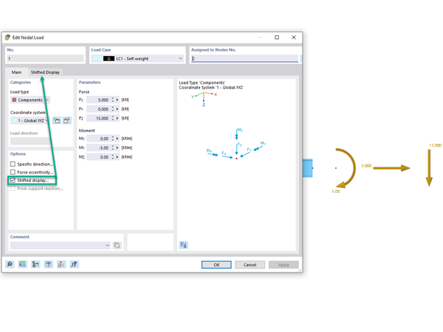
Would you like to display nodal loads or load components that act on one point next to each other? Then use the "Shifted Display" option. This allows you to define offsets in the x, y, and z directions, as well as the size and spacing.
Go to Explanatory Video
Would you like to perform cross-section design checks for cold-formed steel members according to EN 1993‑1‑3? No matter if you design the cold-formed sections from the cross-section library or the general cold-formed (non-perforated) sections from RSECTION – your structural analysis program helps you to determine the effective cross-section, taking into account the local buckling and instability. You can also perform a cross-section check according to EN 1993‑1‑3, 6.1.6. In this case, the internal forces from the calculation using Torsional Warping (7 DOF) are taken into account by means of the equivalent stress check
Go to Explanatory Video
The Torsional Warping (7 DOF) add-on allows you to perform the calculation of member structures in RFEM and RSTAB, taking into account the cross-section warping. You can consider all internal forces (N, Vu, Vv, Mt,pri, Mt,sec, Mu, Mv, Mω) determined in this way in the equivalent stress analysis of the aluminum design. Please Note: This feature is not yet available for the design standard ADM 2020.
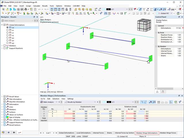
The results for members can be displayed graphically, using the Member Hinges navigator category. The numerical results of member hinges can be found in the Results by Member table category. The Member Hinge Deformations and Member Hinge Forces tables are available for the analysis and documentation of the deformation and force results in the area of member hinges.
The table lists the deformations and forces of each member for the locations specified in the Results Table Manager. There, you can also control which extreme values are displayed.

Note that the definition of the effective lengths in the Aluminum Design add-on is an essential requirement for the stability analysis. For this, define the nodal supports and effective length factors in the input dialog box. Do you want to clearly document the nodal supports and the resulting segments with the associated effective length factors? To check the input data, it is best for you to use the graphic display in the RFEM/RSTAB work window. Thus, you can comprehend the design at any time with minimum effort.

As usual, you enter the structural system and calculate the internal forces in the programs RFEM and RSTAB. You have unlimited access to the extensive material and cross-section libraries. Did you know that you can create general cross-sections using the RSECTION program? That saves you a lot of work.
Don't be afraid of additional windows and input chaos! Aluminum Design is completely integrated into the main programs and automatically takes into account the structure and the available calculation results. You can directly assign further entries for the aluminum design, such as effective lengths, cross-section reductions, or design parameters, to the objects to be designed. You can simply and efficiently select the elements graphically using the [Select] function.

The object types listed below can be graphically assigned to the elements of the structure modeled in the program.
- Nodal supports
- Member shear panels
- Local reductions of member cross-sections
- Member transverse stiffeners
- Member longitudinal welds
- Effective lengths
- Boundary conditions
- Line supports
- Loads
- Member support
- Punching reinforcements
- Mesh refinements
- Surface reinforcements
- Surface results adjustments
- Surface support
- Service classes
- Imperfections
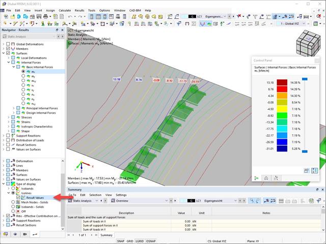
Result values for deformations, internal forces, stresses, and so on, can be displayed on the isolines.

Do you want to consider other loads as masses in addition to the static loads? The program allows that for nodal, member, line and surface loads. For this, you need to select the Mass load type when defining the load of interest. Define a mass or mass components in the X, Y, and Z directions for such loads. For nodal masses, you have an additional option to also specify moments of inertia X, Y, and Z in order to model more complex mass points.

It is often necessary to neglect masses. This is particularly the case when you want to use the output of the modal analysis for the seismic analysis. For this, 90% of the effective modal mass in each direction is required for the calculation. So you can neglect the mass in all fixed nodal and line supports. The program automatically deactivates the associated masses for you.
You can also manually select the objects whose masses are to be neglected for the modal analysis. We have shown the latter in the image for a better view. A user-defined selection is made the and the objects with their associated mass components are selected to neglect the masses.

RFEM allows you to use a special line hinge to model the special properties of the connection between the reinforced concrete slab and masonry wall. This limits the transferable forces of the connection depending on the specified geometry. You guess right: This means that the material cannot be overloaded.
The program develops interaction diagrams that are applied automatically. They represent the various geometric situations and you can use them to determine the correct stiffness.
.png?mw=640&hash=8b43c740f4a91092df759928a6ee21f06f78f8cc)
The calculation of masonry is carried out in compliance with the nonlinear-plastic material law. If the load at any point is higher than the possible load to be resisted, redistribution takes place within the system. This have the simple purpose of restoring the equilibrium of forces. With the successful completion of the calculation, the stability analysis is provided.

- Design of tension, compression, bending, shear, torsion, and combined internal forces
- Consideration of a notch
- Design of compression perpendicular to the grain on the end and intermediate supports with (EC 5) and without reinforcement elements (fully threaded screws)
- Optional shear force reduction at the support (see the Product Feature)
- Design of curved and tapered members
- Consideration of higher strengths for similar components that are close together (factor ksys according to EN 1995‑1‑1, 6.6(1)-(3))
- Option to increase shear resistance for softwood timber according to DIN EN 1995‑1‑1:NA NDP to 6.1.7(2)

- Stability analyses for flexural buckling, torsional buckling, and flexural-torsional buckling under compression
- Import of the effective lengths from the calculation using the Structure Stability add-on
- Graphical input and check of the defined nodal supports and effective lengths for stability analysis
- Determination of the equivalent member lengths for tapered members
- Consideration of Lateral-Torsional Bracing Position
- Lateral-torsional buckling analysis of the structural components subjected to moment loading
- Depending on the standard, a choice between user-defined input of Mcr, analytical method from the standard, and use of internal eigenvalue solver
- Consideration of a shear panel and a rotational restraint when using the eigenvalue solver
- Graphical display of a mode shape if the eigenvalue solver was used
- Stability analysis of structural components with the combined compression and bending stress, depending on the design standard
- Comprehensible calculation of all necessary coefficients, such as the factors for considering moment distribution or interaction factors
- Alternative consideration of all effects for the stability analysis when determining internal forces in RFEM/RSTAB (second-order analysis, imperfections, stiffness reduction, possibly in combination with the Torsional Warping (7 DOF) add-on)

RFEM/RSTAB also provides a range of functions for the case of a fire. The program allows for the automatic generation of load and result combinations for the accidental design situation of fire design. The members to be designed with the corresponding internal forces are imported directly from RFEM/RSTAB. Also, all information about the material and cross-section is stored. You don't need to do anything else.
You only define the parameters relevant for the fire resistance design by assigning a fire resistance configuration to the members and surfaces to be designed. Moreover, you can also make further detailed settings, such as the definition of the fire exposure on one side up to all sides.

You can enter the structural system and calculate the internal forces in the programs RFEM and RSTAB. You have full access to the extensive material and cross-section libraries.
Timber Design is completely integrated into the main programs. At the same time, it automatically takes into account the structure and the available calculation results. You can assign further entries for the timber design, such as effective lengths, cross-section reductions, or design parameters, to the objects to be designed. You can easily select the elements graphically using the [Select] function at many places of the program.

The structural analysis programs RFEM/RSTAB offer you a wide range of automated functions that make your dayily work easier. One of them is the automatic generation of load and result combinations for the accidental design situation of fire design. The members to be designed with the corresponding internal forces are imported directly from RFEM/RSTAB. You don't need to do anything else. The program has also already stored all information about the material and cross-section for you.
By assigning a fire resistance configuration to the members to be designed, you define the parameters relevant for the fire resistance design. Here you can manually specify the critical steel temperature at the design time. Or let the program to determine the temperature determined automatically for a specified fire duration. You can select from various fire temperature curves and fire protection measures. It is also possible to make further detailed settings, such as the definition of the fire exposure on all sides or three sides

The Torsional Warping (7 DOF) add-on provides you with numerous new possibilities. For example, you can perform the calculation of member structures in RFEM and RSTAB, taking into account the cross-section warping. You can consider the resulting internal forces (N, Vu, Vv, Mt,pri, Mt,sec, Mu, Mv, Mω) in the equivalent stress analysis of the steel design. Please note: This feature is currently not available for the design standards AISC 360‑16 and GB 50017.

Do you want to perform a stability analysis in the Steel Design add-on? Then it is absolutely necessary to define the effective lengths. To do this, define the nodal supports and effective length factors in the input dialog box. For easy documentation and a comprehensible check of the entries, you can also graphically display the nodal supports and the resulting segments with the corresponding effective length factor in the work window of RFEM/RSTAB.

You can display the existing stresses and strains of a concrete cross-section and the reinforcement as a 3D stress image or 2D graphic. Depending on which results do you select in the result tree of the design details, the stresses or strains are displayed to you in the defined longitudinal reinforcement under the load actions or the limit internal forces.
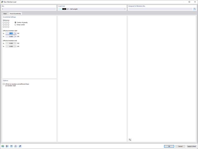
Always keep an eye on the stability of your structures: You can now consider eccentricities for nodal and member loads.

Do you have great respect for the ravages of time? After all, it eventually gnaws at your construction projects. Use the Time-Dependent Analysis (TDA) add-on to consider the time-dependent material behavior of members. Long-term effects, such as creep, shrinkage, and aging, can influence the distribution of internal forces, depending on the structure. Prepare for this optimally with this add-on.

By solving the numerical flow problem, you can obtain the following results on and around the model:
- Pressure on structure surface
- Coefficient Cp distribution on the structure surfaces
- Pressure field about the structure geometry
- Velocity field about the structure geometry
- Turbulence k-ω field about the structure geometry
- Turbulence k-ε field about the structure geometry
- Velocity vectors about the structure geometry
- Streamlines about the structure geometry
- Forces on member-shaped structures that were originally generated from member elements
- Convergence diagram
- Direction and size of the flow resistance of the defined structures
Despite this amount of information, RWIND 2 remains clearly arranged, as is typical for the Dlubal programs. You can specify freely definable zones for a graphic evaluation. Voluminously displayed flow results about the structure geometry are often confusing – you know the problem for sure. That's why RWIND Basic provides freely movable section planes for the separate display of the "solid results" in a plane. For the 3D branched streamline result, you have an option to select between a static and an animated display in the form of moving line segments or particles. This option helps you to represent the wind flow as a dynamic effect.
You can export all results as a picture or, especially for the animated results, as a video.