The snow load generator can generate snow loads as member loads or surface loads.
Additional snow loads such as drifted snow loads, snow overhangs, and snow guards can be taken into account as well.
The following standards are available:
-
 EN 1991-1-3 (incl. National Annexes)
 -
 DIN 1055-5
 -
 CTE DB-SE-AE
 -
 ASCE/SEI 7-16

Wind loads can be automatically generated as member loads or area loads on the following structural components (optional with internal pressure for open buildings):
- Vertical walls
- Flat roofs
- Monopitch roofs
- Duopitch/troughed roofs
- Vertical walls with roof
The following standards are available:
-
EN 1991-1-3 (incl. National Annexes)
-
DIN 1055-4
-
CTE DB-SE-AE
-
ASCE/SEI 7-16
Area loads can be automatically converted into member or line loads. There are 3 options available for this:
- Generate Member Loads from Area Load via Plane
- Member loads from area loads via cells
- Line loads from surface loads on openings
In the case of member loads from area loads, a plane has to be defined via corner nodes or cells have to be selected in the graphic. The area load can either be applied to the entire surface or only the effective or projected surface of the members.
For the 'Line Loads from Area Loads on Openings' function, the corresponding openings are selected.
Online Manual RFEM | Member Loads from Area Loads via Plane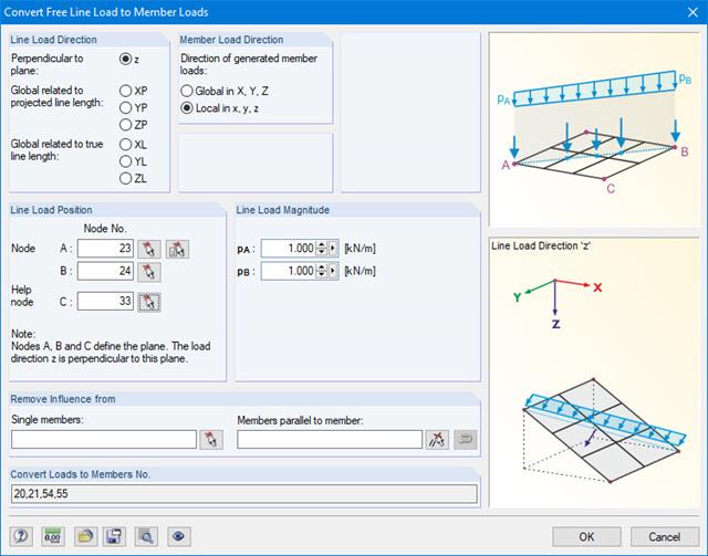
For pure member models such as grillages, you can define free line loads (e.g. from conveyor belts) and transfer them proportionally to members.
More Information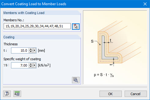
Coating loads can be generated as member loads from ice loads, claddings, and so on.
For this, you only have to specify the thickness and specific weight of the coating.
Manual RFEM 5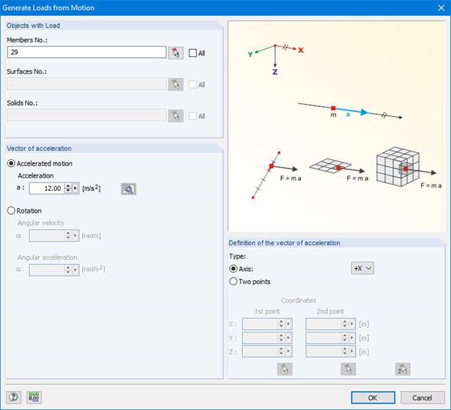
This generator creates loads as a result of an acceleration or rotation (e.g. from tower cranes), which acts on specific objects of the model.
The mass is determined from the self-weight.
More Information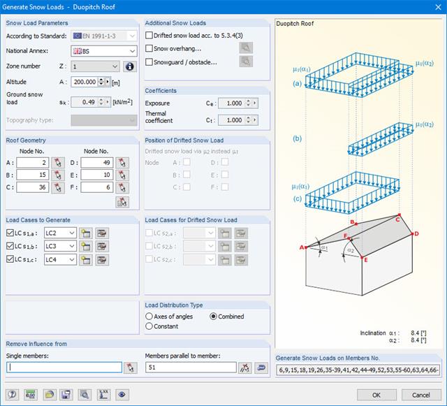
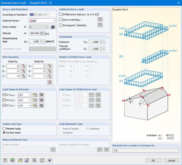
Snow loads can be generated as member loads on flat/monopitch roofs and duopitch roofs.
Additional snow loads such as drifted snow loads, snow overhangs, and snow guards can be taken into account as well.
The following standards are available:
-
EN 1991-1-3 (incl. National Annexes)
-
DIN 1055-5
-
CTE DB-SE-AE
-
ASCE/SEI 7-16
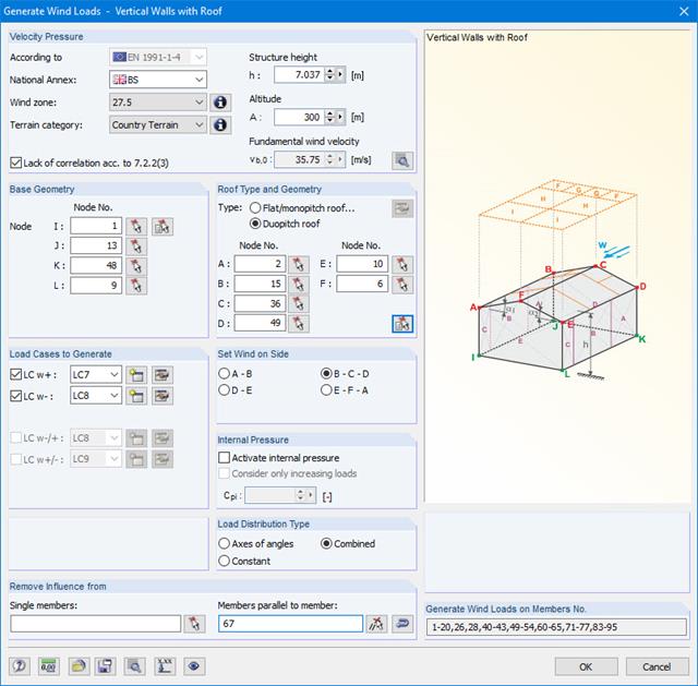
Wind loads can be automatically generated as member loads on the following structural components (optional with internal pressure for open buildings):
- Vertical walls
- Flat roofs
- Monopitch roofs
- Duopitch/troughed roofs
- Vertical walls with roof
The following standards are available:
-
EN 1991-1-3 (incl. National Annexes)
-
DIN 1055-4
-
CTE DB-SE-AE
-
ASCE/SEI 7-16
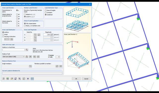
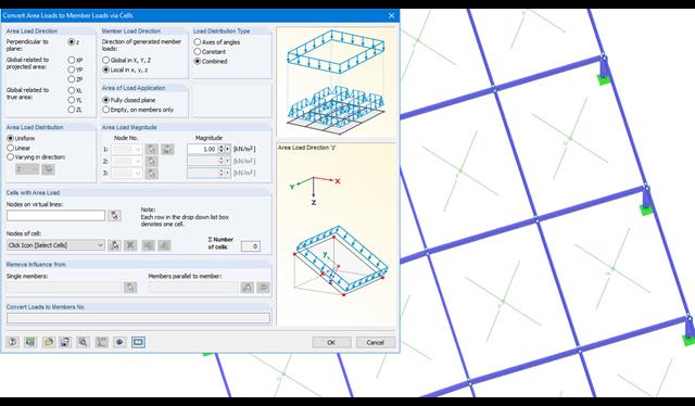
Area loads can be automatically converted into member loads. There are 2 options available for this:
- Generate Member Loads from Area Load via Plane
- Member loads from area loads via cells
Depending on the selected option, you either have to define a plane via corner nodes or select cells in the graphic. The area load can either be applied to the entire surface or only the effective or projected surface of the members.
Online Manual RFEM | Member Loads from Area Loads via Plane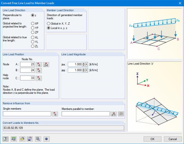
With this generator, you can e.g. for grillages, you can define free line loads (e.g. from conveyor belts) and prorate them to members.
More Information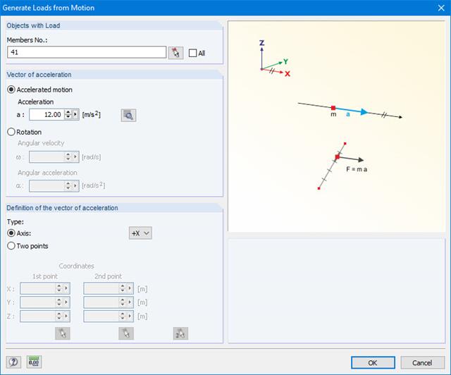
This generator creates loads as a result of an acceleration or rotation that acts on specific objects of the model.
The mass is determined from the self-weight.
More Information
- Design of tension, compression, bending, shear, combined internal forces, and torsion
- Stability analysis for flexural buckling, torsional buckling, and lateral-torsional buckling
- Optional application of discrete lateral supports to beams
- Deformation analysis (serviceability)
- Cross-section optimization
- Wide range of cross-sections available, such as rolled I-sections, channel sections, rectangular hollow sections, angles, T-sections. Welded sections: I-shaped (symmetrical and asymmetrical about major axis), channel sections (symmetrical about major axis), rectangular hollow sections (symmetrical and asymmetrical about major axis), angles, round pipes, and round bars
- Clearly arranged result tables
- Detailed result documentation including references to design equations of the used standard
- Various filter and sorting options of results, including result lists by member, cross-sections, x-location, or by load case, load and result combination
- Result table of member slenderness and governing internal forces
- Parts list with weight and solid specifications
- Seamless integration in RFEM/RSTAB
.png?mw=640&hash=721e09a7520480378145fa75eaabf5a5bed8f7e3)
- Full integration in RFEM/RSTAB including import of all relevant information and internal forces
- Determination of stress ranges for the available load cases and load or result combinations
- Free assignment of detail categories on the available stress points of the cross-section
- User-defined specification of damage equivalent factors
- Design of members and sets of members according to EN 1993-1-9
- Optimization of cross-sections with the option to transfer the data to RFEM/RSTAB
- Detailed result documentation with references to design equations used
- Various filter and sorting options of results, including result lists by member, cross-sections, x-location, or by load case, load and result combination
- Visualization of the design criterion on RFEM/RSTAB model
- Data export to MS Excel
- Full integration in RFEM/RSTAB with import of relevant internal forces
- Design checks for the elastic-elastic and elastic-plastic methods
- Graphical selection of members and sets of members for design
- Analysis for several load and design cases
- Design based on the buckling field parameters integrated in the cross-section library for the cross-section parts supported on one and both sides
- Optional determination of shear stresses according to comment on El. (745)
- Possibility to consider the weld thickness in the design of welded cross-sections, which has the effect of a shortening of the cross-section part width
- Cross-section optimization with the option to export modified cross-sections
- Simple definition of unit loads in RFEM model
- Simple definition of the points on members, surfaces, and supports to be analyzed
- Numerical results and graphical display of unit load or designed point results
- Detailed printout report, including all model and load data of each designed point and unit load used
- Design of member ends, members, nodal supports, nodes, and surfaces
- Consideration of specified design areas
- Check of cross-section dimensions
- Design according to EN 1995-1-1 (European Timber Standard) with the respective National Annexes + DIN 1052 + DSTV DIN EN 1993-1-8 + ANSI / AWC - NDS 2015 (US Standard)
- Design of various materials, such as steel, concrete, and others
- No necessary linking to specific standards
- Extensible library including timber fasteners (SIHGA, Sherpa, WÜRTH, Simpson StrongTie, KNAPP, PITZL) and steel fasteners (standardized connections in steel building design according to EC 3, M-connect, PFEIFER, TG-Technik)
- Ultimate load capacities of timber beams by the companies STEICO and Metsä Wood available in the library
- Connection to MS Excel
- Optimization of connecting elements (the most utilized element is calculated)
- Parameterized load positions of different concentrated, distributed, surface, and axle loads
- Access to a library with different axle load models
- Favorable or unfavorable load application considering influence lines and surfaces
- Summary of several moving loads in one load scheme
- Generation of a result combination for determination of the most unfavorable internal forces
- Possible to save load schemes for further use in other structures
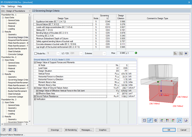
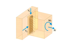
It is possible to perform the following designs:
- Equilibrium limit state design
- Uplift limit state design
- Ground failure (soil contact pressure) design
- Strong eccentric loads design
- Design of foundation torsion and limitation of gaping joint
- Sliding design
- Settlement calculation
- Bending failure design of the plate and bucket
- Punching shear design
Foundation and bucket dimensions can be user-defined or determined by the module. You can edit the determined reinforcement manually. In this case, the designs are updated automatically.
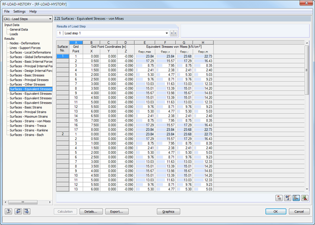
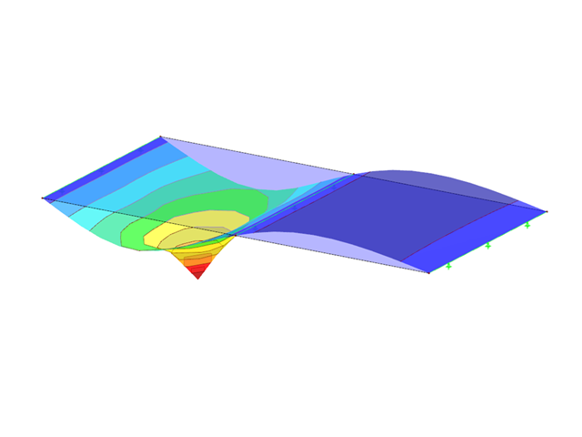
After the calculation, you can evaluate the results of the individual load steps directly in the module windows or graphically in a structural model.
The results include, for example, deformations, stresses, and internal forces of surfaces, as well as deformations and stresses of solids. It is possible to export the result combinations for each load step to RFEM. You can use these enveloping combinations for further designs in the other RFEM add-on modules.
All input data and results of the add-on module are part of the global RFEM printout report.
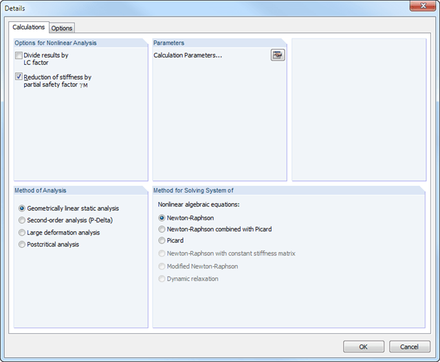
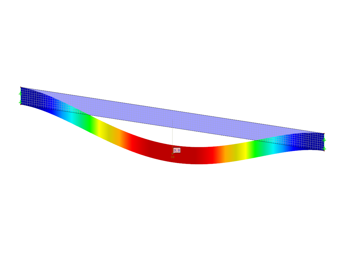
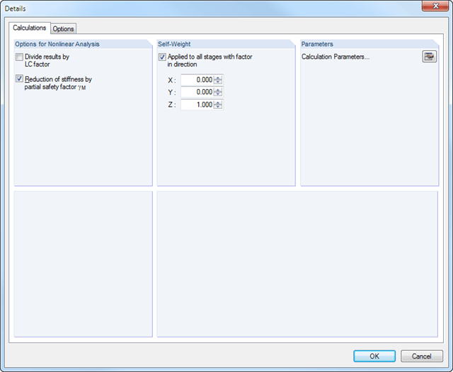
The calculation is performed successively for each load step. Permanent (plastic) deformations of previous load steps are considered when calculating further load steps. This way, it is also possible to perform a calculation with a structure relief.
The loads of the individual steps are added up (depending on the signs) throughout the calculation process. You can freely select the method of analysis (linear static, second-order, large deformation, and postcritical analysis). Furthermore, the module manages the global calculation settings.
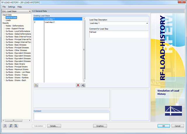
After defining the entire model and loading in RFEM, it is possible to enter load steps and descriptions in the 1.1 General Data window.
In Window 1.2 Loads, you can assign the load cases or load combinations to the different load increments. It is possible to multiply them by a load factor.
.png?mw=640&hash=31ebb9c47d4f8334d4a27ff248233fc0442a2e72)
- Simple definition of load increments
- Simple assignment of load cases and load combinations to load increments
- Consideration of plastic deformations (isotropic hardening behavior) of previous load increments
- Numerical and graphical display of results (deformations, support forces, internal forces, stresses, strains, and so on) for individual load increments
- Detailed printout report including result documentation for all load increments
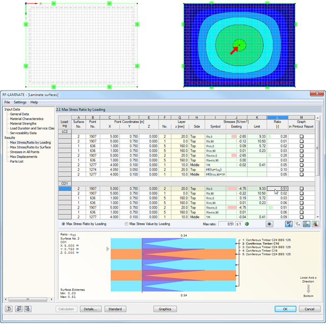
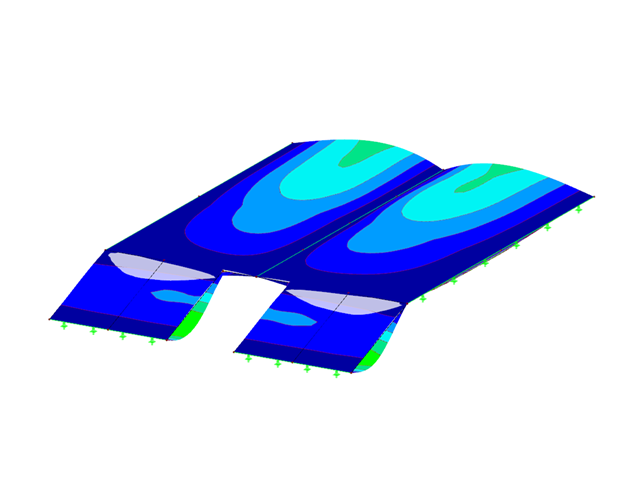
After the calculation, the maximum stresses, stress ratios, and displacements are displayed by load case, surface, or grid points. The design ratio can be related to any kind of stress type. The current location is highlighted by color in the RFEM model.
In addition to the result evaluation in tables, it is possible to display the stresses and stress ratios graphically in the RFEM work window. For this, you can adjust the colors and values assigned in the panel.
It is necessary to select load cases, load combinations, and result combinations for the ultimate and the serviceability limit state design. After selecting the surfaces to be designed, you can define the relevant material model.
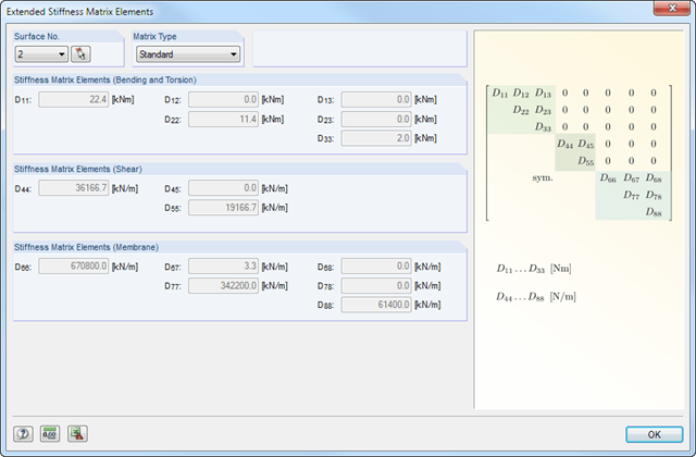
The structure of layers forming the basis for the stiffness calculation can vary. You can adjust the parameters defined by the selected material model according to your individual needs. The 3*3 matrix of the layers is modifiable as well. In this way completely free selection when generating the stiffnesses is provided.
The limit stresses of each layer are defined by the selected material. These values can be customized as well.
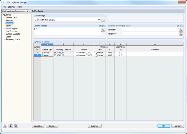
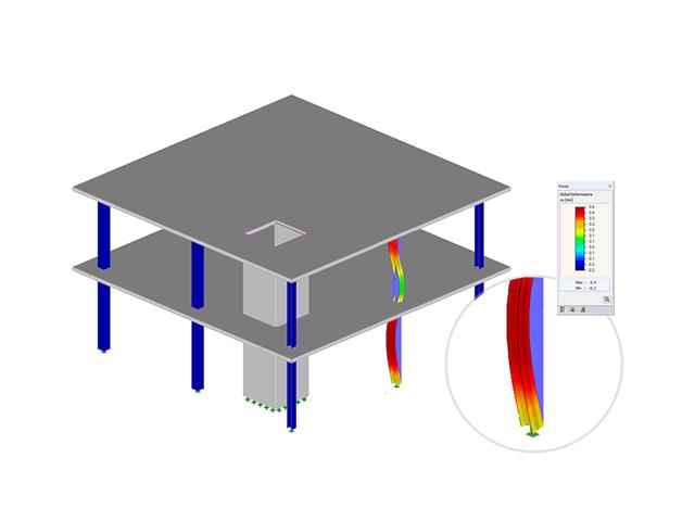
The calculation of the "Permanent Loads" is performed in compliance with the large deformation analysis successively for each construction stage.
The resulting geometry differences between the ideal and the deformed structural system from the previous construction stage are compared in the background. The next construction stage is built on top of the stressed system from the previous construction stage.
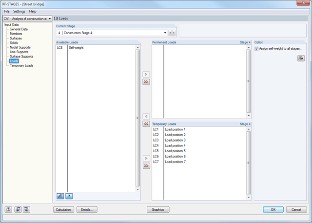
After creating the entire structure in RFEM/RSTAB, the individual structural components as well as load cases and combinations are assigned to the corresponding construction stages. For each construction stage, you can modify for example release definitions of members and supports.
Thus, it is possible to model structural modifications, such as those that occur when bridge girders are successively grouted or when columns are settled. The load cases and load combinations already created in RFEM/RSTAB are divided into "Permanent Loading" and "Temporary Loading" in the add-on module.
The defined temporary loads are superimposed by permanent loads. This way, it is possible to determine the maximum internal forces of different crane positions or to consider temporary mounting loads available only in one construction stage.
- Simple definition of construction stages in the RFEM/RSTAB structure including visualization
- Addition, removal, and modification of member, surface, and solid properties (such as member hinges, surface eccentricities, degrees of freedom for supports, and others)
- Optional superposition of construction stages with additional temporary loads; for example, mounting loads or mounting cranes, and others
- Consideration of nonlinear effects such as failure of a tension member, elastic foundations, or nonlinear supports
- Numerical and graphical result display for individual construction stages or as an envelope (Max/Min) of all construction stages
- Detailed printout report including all structural and load data of each construction stage
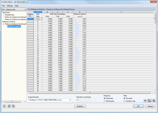
After defining the points to be analyzed, the module generates influence lines and surfaces. Then, all result diagrams are available in result windows sorted by points and unit loads applied on members, surfaces, and supports.
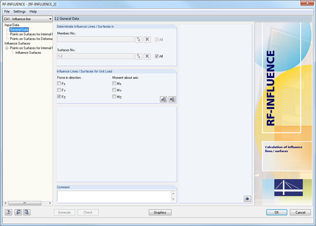
Member and surface models created in RFEM are analyzed at a particular point by applying a unit load with the previously defined load magnitude and direction. The module determines the way the unit load affects the internal forces at the inspected point.
This simulation is represented graphically by an influence line or influence surface resulting from the load magnitude of the force or moment at the inspected model point. The graphical representation can be used for further analyses or to check the behavior of the model.
The RF-INFLUENCE add-on module determines the influence lines and surfaces of models containing beams and surfaces.
- Calculation of models consisting of member, shell, and solid elements
- Import of axial forces from a load case or combination
- Non-linear stability analysis
- Optional consideration of axial forces from initial prestress
- Four equation solvers for effective calculation of various structural models
- Optional consideration of stiffness modifications in RFEM
- Calculation of buckling modes of unstable models
- Determination of stability mode greater than the user-defined load increment factor (Shift method)
- Optional determination of the mode shapes of unstable models (to identify the cause of instability)
- Visualization of stability mode
- Basis for analysis using imperfect equivalent structures in RF-IMP