14 Wyniki
Wyświetl wyniki:
Sortuj według:
Słup w kształcie litery W zgodny z normą ASTM A992 14x132 jest obciążony zadanymi osiowymi siłami ściskającymi. Słup jest przegubowy na górze i na dole w obu osiach. Należy określić, czy słup jest w stanie wytrzymać obciążenie pokazane na rysunku 1 na podstawie LRFD i ASD.
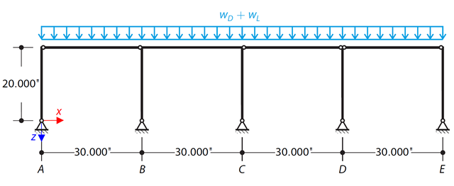
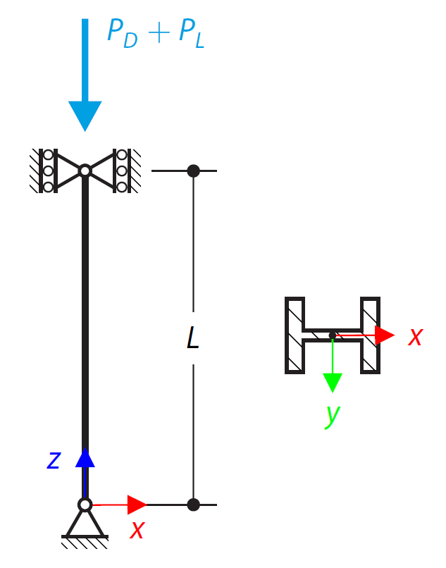
Za pomocą LRFD i ASD należy określić wymagane wytrzymałości i współczynniki długości efektywnej dla słupów z materiału ASTM A992 w ramie skręcania pokazanej na rysunku 1 dla maksymalnej kombinacji obciążeń grawitacyjnych.
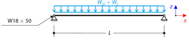
Rozważ belkę ASTM A992 W 18x50 dla stałych i równomiernych obciążeń stałych i ruchomych, jak pokazano na Rysunku 1. Pręt jest ograniczony do maksymalnej nominalnej głębokości wynoszącej 18 cali. Ugięcie pod obciążeniem użytkowym jest ograniczone do L/360. Belka jest swobodnie podparta i usztywniona. Sprawdź dostępną wytrzymałość na zginanie wybranej belki na podstawie LRFD i ASD.
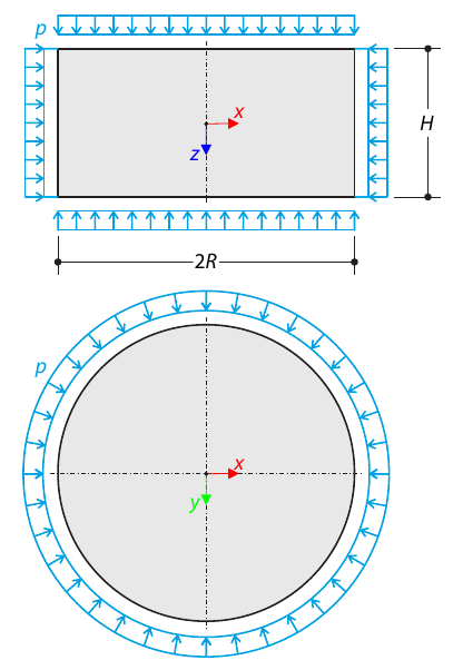
Walec wykonany z gruntu sprężysto-plastycznego jest poddawany trójosiowym warunkom testowym. Celem jest określenie granicznego naprężenia pionowego dla zniszczenia naprężenia od ścinania, pomijając ciężar własny. Uwzględniane jest początkowe naprężenie hydrostatyczne 100 kPa.
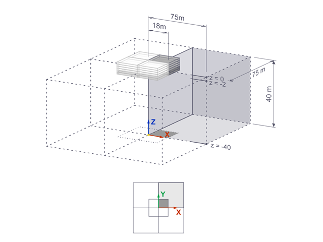
Osiadania sztywnego fundamentu kwadratowego na glinie jeziornej [1] są obliczane w programie RFEM. Modelowana jest jedna czwarta fundamentu. Fundament ma szerokość 75,0 m po obu stronach. Do wygenerowania wyników wykorzystywane są etapy budowy.
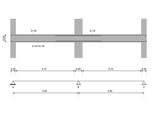
W tym przykładzie obliczeniowym obliczane są wartości nośności sił tnących na belkach zgodnie z EN 1998-1, 5.4.2.2 i 5.5.2.1 oraz nośność słupów przy zginaniu zgodnie z 5.2.3.3(2 ). System składa się z dwuprzęsłowej belki żelbetowej o rozpiętości 5,50 m. Belka jest częścią układu ramowego. Otrzymane wyniki są porównywane z wynikami w [1].
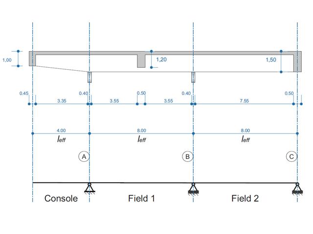
Belka żelbetowa została zaprojektowana jako belka dwuprzęsłowa na wsporniku. Przekrój zmienia się na całej długości wspornika (przekrój o zmiennym przekroju). Obliczane są siły wewnętrzne oraz wymagane zbrojenie podłużne i zbrojenie na ścinanie dla stanu granicznego nośności.
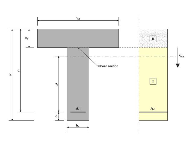
W tym przykładzie ścinanie na granicy między betonem wylanym w różnym czasie a odpowiednim zbrojeniem jest określane zgodnie z DIN EN 1992-1-1. Wyniki uzyskane w programie RFEM 6 zostaną porównane z poniższymi obliczeniami ręcznymi.
Model oparty jest na przykładzie 4 z [1]: Płyta podparta punktowo. Siły wewnętrzne i wymagane zbrojenie podłużne można znaleźć w przykładzie weryfikacji 1022. W tym przykładzie przebijanie jest rozpatrywane w osi B/2.
Model oparty jest na przykładzie 4 z [1]: Płyta podparta punktowo.
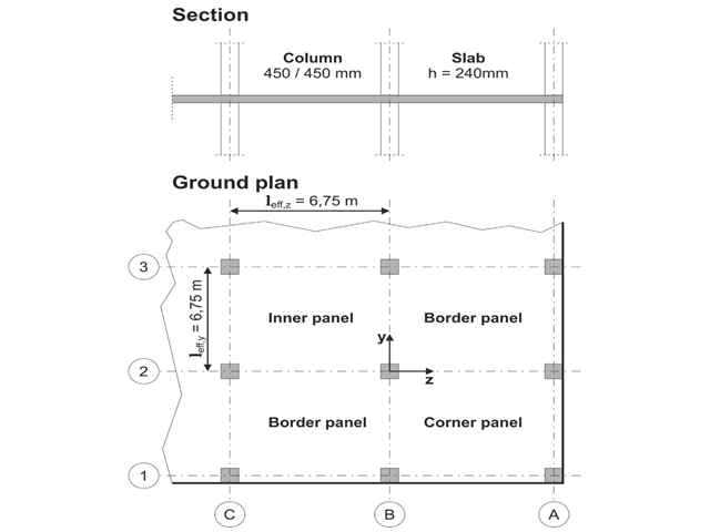
Należy zaprojektować płaską płytę budynku biurowego o wrażliwych na zarysowania ścianach lekkich. Należy zbadać panele wewnętrzne, brzegowe i narożne. Słupy i płyta są połączone monolitycznie. Słupy skrajne i narożne są zlicowane z krawędzią płyty. Osie słupów tworzą siatkę kwadratową. Jest to układ sztywny (budynek usztywniony ścianami usztywniającymi).
Budynek biurowy ma 5 kondygnacji i ma wysokość 3.000 m. Warunki środowiskowe, które należy przyjąć, określane są jako „zamknięte przestrzenie wewnętrzne”. Występują głównie oddziaływania statyczne.
Celem tego przykładu jest określenie momentów w płycie i wymaganego zbrojenia nad słupami przy pełnym obciążeniu.