22 Wyniki
Wyświetl wyniki:
Sortuj według:
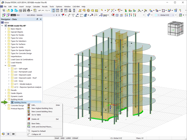
W programie RFEM 6 analizę sejsmiczną można przeprowadzić za pomocą modułów dodatkowych Analiza modalna i Analiza spektrum odpowiedzi. Zaraz po zakończeniu analizy spektralnej za pomocą rozszerzenia Model budynku można wyświetlić oddziaływania kondygnacji, przemieszczenia kondygnacji i siły w ścianach usztywniających.

Jeżeli, na przykład, do określenia sił wewnętrznych ma zostać zastosowany model czysto powierzchniowy, ale wymiarowanie komponentu nadal odbywa się na modelu prętowym, można skorzystać z belki wynikowej.

Rozszerzenie Wymiarowanie betonu umożliwia wymiarowanie słupów betonowych zgodnie z ACI 318-19. Poniższy artykuł potwierdzi wymiarowanie zbrojenia w rozszerzeniu Wymiarowanie betonu przy użyciu równań analitycznych krok po kroku zgodnie z normą ACI 318-19, w tym wymagane zbrojenie podłużne, pole przekroju brutto i rozmiar/rozstaw ściągu.

W tym artykule opisano, w jaki sposób płaska płyta budynku mieszkalnego jest modelowana w programie RFEM 6 i wymiarowana zgodnie z Eurokodem 2. Płyta ma grubość 24 cm i jest podparta na słupach o długości 45/45/300 cm w rozstawie co 6,75 m (rysunek 1). Słupy są modelowane jako sprężyste podpory węzłowe poprzez zdefiniowanie sztywności sprężystej na podstawie warunków brzegowych (rysunek 2). Jako materiały wybrano beton C35/45 i stal zbrojeniową B 500 S (A).

Zgodnie z EN 1992-1-1 [1] belka jest prętem, którego rozpiętość jest nie mniejsza niż 3-krotna całkowita wysokość przekroju. W przeciwnym razie element konstrukcyjny należy traktować jako belkę-ścianę. Zachowanie belek-ścian (tj. belek o rozpiętości mniejszej niż 3-krotna wysokość przekroju) różni się od zachowania belek-ścian (tj. belek o rozpiętości trzykrotnie większej niż wysokość przekroju).
Projektowanie belek-ścian jest jednak często konieczne podczas analizy elementów konstrukcyjnych konstrukcji żelbetowych, ponieważ są one wykorzystywane do budowy nadproży okiennych i drzwiowych, podciągów i podciągów, połączeń między płytami dwupoziomowymi oraz konstrukcji ramowych.
Projektowanie belek-ścian jest jednak często konieczne podczas analizy elementów konstrukcyjnych konstrukcji żelbetowych, ponieważ są one wykorzystywane do budowy nadproży okiennych i drzwiowych, podciągów i podciągów, połączeń między płytami dwupoziomowymi oraz konstrukcji ramowych.

W tym artykule opisano na przykładzie płyty z betonu włóknistego, które wpływają na zastosowanie różnych metod całkowania i różnej liczby punktów całkowania na wynik obliczeń.

W tym artykule opisujemy, w jaki sposób można używać rozszerzenia Skręcanie skrępowane (7 stopni swobody) i Stateczność konstrukcji w celu uwzględnienia deplanacji przekroju jako dodatkowego stopnia swobody podczas analizy stateczności.
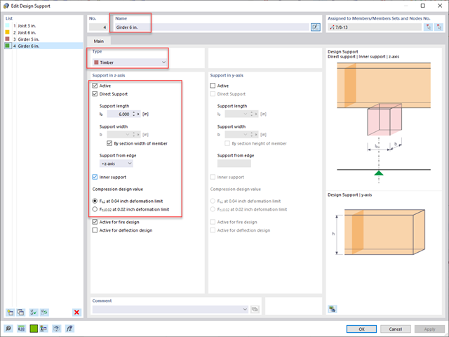
Standardowym rozwiązaniem w konstrukcji prętów drewnianych jest możliwość łączenia mniejszych prętów poprzez podparcie na większym dźwigarze. Dodatkowo warunki na końcach pręta mogą uwzględniać podobną sytuację, w której belka jest oparta na podporze. W obu przypadkach belka musi być zaprojektowana tak, aby uwzględniała nośność w poprzek włókien zgodnie z NDS 2018 s. 3.10.2 i CSA O86:19 punkty 6.5.6 i 7.5.9. W ogólnych programach do projektowania statyczno-wytrzymałościowego zazwyczaj nie jest możliwe przeprowadzenie pełnej kontroli obliczeń, ponieważ powierzchnia docisku jest nieznana. Jednak w programie RFEM 6 nowej generacji i rozszerzeniu Projektowanie konstrukcji drewnianych dodana funkcja "podpór obliczeniowych" umożliwia teraz użytkownikom uwzględnienie docisku NDS i CSA prostopadle do warunków obliczeniowych.

Obliczenia ze względu na zmęczenie zgodnie z EN 1992-1-1 należy przeprowadzać w przypadku elementów konstrukcyjnych, które są poddane działaniu dużych zakresów naprężeń i/lub wielu zmianom obciążenia. W takim przypadku obliczenia dla betonu i zbrojenia są przeprowadzane osobno. Dostępne są dwie alternatywne metody obliczeniowe.
W tym artykule pokazano praktyczny przykład, jak określać współczynniki obciążenia krytycznego i odpowiadające im kształty drgań w programie RFEM 6.