101 Wyniki
Wyświetl wyniki:
Sortuj według:

- 002876
- Ogólne informacje
- Projektowanie konstrukcji betonowych RFEM 6
- Projektowanie konstrukcji betonowych RSTAB 9
W przypadku obliczeń betonu wyniki zbrojenia można wyświetlić w tabelach osobno w zależności od sytuacji obliczeniowych.

- 002842
- Ogólne informacje
- Analiza naprężeniowo-odkształceniowa RFEM 6
- Analiza naprężeniowo-odkształceniowa RSTAB 9
W rozszerzeniu Analiza naprężeniowo-odkształceniowa można użyć opcji, aby określić zależne od znaku naprężenia graniczne za pomocą składowej naprężenia.

- 002829
- Ogólne informacje
- Analiza naprężeniowo-odkształceniowa RFEM 6
- Analiza naprężeniowo-odkształceniowa RSTAB 9
W rozszerzeniu Analiza naprężeniowo-odkształceniowa można zdefiniować cykl naprężeń granicznych zależny od elementu i uwzględnić go w obliczeniach.

W rozszerzeniu Projektowanie konstrukcji betonowych dla programu RFEM 6 można przeprowadzić obliczenia odporności ogniowej ścian i płyt żelbetowych zgodnie z uproszczoną metodą tabelaryczną (EN 1992-1-2, rozdział 5.4.2 oraz tabele 5.8 i 5.9).

W rozszerzeniu Projektowanie konstrukcji betonowych można zdefiniować istniejące pionowe zbrojenie na ścinanie. Jest to następnie uwzględniane przy obliczaniu wytrzymałości na przebicie.

- 002801
- Ogólne informacje
- Projektowanie konstrukcji betonowych RFEM 6
- Projektowanie konstrukcji betonowych RSTAB 9
Masz indywidualne przekroje słupów i ścian o różnej geometrii, które wymagają obliczenia nośności na przebicie?
Nie ma problemu. W programie RFEM 6 można przeprowadzić obliczenia na przebicie nie tylko dla przekrojów prostokątnych i okrągłych, ale także dla dowolnego kształtu przekroju.

Wynik obliczeń sejsmicznych jest podzielony na dwie sekcje: wymagania dotyczące prętów i połączeń.
"Wymagania sejsmiczne" zawierają Wymaganą wytrzymałość na zginanie i Wymaganą wytrzymałość na ścinanie połączenia belka-słup dla ram sprężystych. Są one wyszczególnione w zakładce 'Połączenia ram momentowych według prętów'. W przypadku ram stężonych w zakładce 'Połączenie stężone według pręta' podawana jest Wymagana wytrzymałość połączenia na rozciąganie oraz Wymagana wytrzymałość połączenia na ściskanie stężeń.
Przeprowadzone kontrole obliczeń są przedstawiane w tabelach. W szczegółach kontroli obliczeń w przejrzysty sposób przedstawione są wzory i odniesienia do normy.

Rozszerzenie Analiza modalna umożliwia automatyczne zwiększanie poszukiwanych wartości własnych do momentu osiągnięcia zdefiniowanego współczynnika efektywnej masy modalnej. Uwzględniane są wszystkie kierunki translacyjne, które zostały aktywowane jako masy do analizy modalnej.
W ten sposób można łatwo obliczyć wymagane 90% efektywnej masy modalnej dla metody spektrum odpowiedzi.

- 002733
- Ogólne informacje
- Projektowanie konstrukcji stalowych RFEM 6
- Projektowanie konstrukcji stalowych RSTAB 9
Rozszerzenie Projektowanie konstrukcji stalowych umożliwia przeprowadzanie obliczeń sejsmicznych prętów stalowych zgodnie z AISC 341-16.
W tym celu dostępnych jest pięć typów systemów SFRS (Seismic Force-Resisting Systems).

W przypadku analizy spektrum odpowiedzi modeli budynków można wyświetlić współczynniki wrażliwości dla kierunków poziomych według kondygnacji.
Dzięki tym kluczowym wartościom można zinterpretować wrażliwość na efekty stateczności.

- 002720
- Ogólne informacje
- Analiza stateczności konstrukcji RFEM 6
- Analiza stateczności konstrukcji RSTAB 9
Stosując modalny współczynnik istotności (MRF) można ocenić, w jakim stopniu poszczególne elementy konstrukcyjne przyczyniają się do powstania rzeczywistego kształtu wyboczenia. Obliczenia opierają się na energii względnego odkształcenia sprężystego każdego pojedynczego pręta.
Dzięki MRF można rozróżnić lokalne i globalne kształty wyboczenia. Jeżeli kilka prętów ma znaczny MRF (np. > 20%), bardzo prawdopodobna jest niestateczność całej konstrukcji lub jej części. Jeżeli jednak suma wszystkich MRF dla kształtu drgań wynosi około 100%, należy spodziewać się lokalnego problemu ze statecznością (np. wyboczenia pojedynczego pręta).
Ponadto MRF może być wykorzystany do określenia obciążeń krytycznych i równoważnych długości wyboczeniowych poszczególnych prętów (np. do analizy stateczności). Kształty wyboczenia, dla których dany pręt ma małe wartości MRF (np. <20%), mogą zostać w tym kontekście pominięte.
MRF jest wyświetlany według kształtów wyboczenia w tabeli wyników w sekcji Analiza stateczności --> Wyniki według prętów --> Długości efektywne i obciążenia krytyczne.

- 002691
- Ogólne informacje
- Projektowanie konstrukcji betonowych RFEM 6
- Projektowanie konstrukcji betonowych RSTAB 9
W rozszerzeniu Projektowanie konstrukcji betonowych można przeprowadzić uproszczone obliczenia odporności ogniowej słupów (Rozdział 5.3.2) i belek (Rozdział 5.6), zgodnie z EN 1992-1-2.
W przypadku uproszczonych obliczeń odporności ogniowej dostępne są następujące metody weryfikacji:
- Słupy: Minimalne wymiary przekroju prostokątnego i okrągłego wg tabeli 5.2a oraz równania 5.7 do obliczania czasu ekspozycji pożarowej
- Belki: Minimalne wymiary i odległości między środkami zgodnie z Tabelą 5.5 i Tabelą 5.6
Siły wewnętrzne do obliczeń odporności ogniowej można wyznaczyć przy użyciu dwóch metod.
- 1: W tym przypadku siły wewnętrzne z wyjątkowej sytuacji obliczeniowej są bezpośrednio uwzględniane w obliczeniach.
- 2: Siły wewnętrzne z obliczeń w temperaturze normalnej są redukowane za pomocą współczynnika Eta,fi (ηfi) i są następnie wykorzystywane do obliczeń odporności ogniowej.
Ponadto istnieje możliwość modyfikacji rozstawu osi zgodnie z równ. 5.5.

Rozszerzenie Projektowanie konstrukcji betonowych umożliwia wymiarowanie prętów i powierzchni ze względu na zmęczenie zgodnie z EN 1992-1-1, rozdział 6.8.
W przypadku obliczeń zmęczenia można opcjonalnie wybrać dwie metody lub poziomy obliczeniowe w konfiguracjach obliczeniowych:
- Poziom obliczeniowy 1: Obliczenia uproszczone wg. do 6.8.6 i 6.8.7(2) Kryterium uproszczone jest stosowane dla częstych kombinacji oddziaływań zgodnie z EN 1992-1-1, rozdział 6.8.6 (2) oraz EN 1990, równ. (6.15b) wraz z obciążeniami od ruchu drogowego w stanie użytkowalności. Dla stali zbrojeniowej sprawdzany jest maksymalny zakres naprężeń zgodnie z 6.8.6. Naprężenie ściskające w betonie jest określane za pomocą górnego i dolnego dopuszczalnego naprężenia zgodnie z 6.8.7(2).
- Poziom analizy 2: Obliczanie równoważnego naprężenia niszczącego zgodnie z 6.8.5 i 6.8.7(1) (uproszczone obliczenia na zmęczenie): Obliczenia z wykorzystaniem zakresów równoważnych naprężeń niszczących są przeprowadzane dla kombinacji zmęczeniowych, zgodnie z EN 1992-1-1, rozdział 6.8.3, równ. (6.69) o specyficznie zdefiniowanym oddziaływaniu cyklicznym Qfat .

W rozszerzeniu Projektowanie konstrukcji betonowych można przeprowadzać obliczenia sejsmiczne dla prętów żelbetowych zgodnie z EC 8. Są to między innymi następujące funkcje:
- Konfiguracje obliczeń sejsmicznych
- Rozróżnianie klas ciągliwości DCL, DCM, DCH
- Możliwość przeniesienia współczynnika odpowiedzi z analizy dynamicznej
- Sprawdzenie wartości granicznej współczynnika odpowiedzi
- Weryfikacja nośności dla "Wytrzymały słup - słaba belka"
- Uszczegółowienie i reguły szczególne dla współczynnika ciągliwości krzywizny
- Uszczegółowienie i reguły szczególne dla ciągliwości lokalnej

W rozszerzeniu Projektowanie konstrukcji stalowych można przeprowadzić kontrolę obliczeń stateczności i przekrojów profili formowanych na zimno według EN 1993-1-3, zgodnie z punktami 6.1.2 - 6.1.5 i 6.1.8 - 6.1.10.
Przejdź do filmu
Teraz w rozszerzeniu Projektowanie konstrukcji betonowych można wymiarować elementy wykonane z betonu zbrojonego włóknami zgodnie z wytyczną "DAfStb Steel Fiber-Reinforced Concrete".
Ta opcja jest dostępna dla obliczeń zgodnie z EN 1992-1-1. Obliczenia zgodnie z wytyczną DAfStb są przeprowadzane po przypisaniu betonu typu "Fibrobeton" do elementu konstrukcyjnego z betonu zbrojonego.
Przejdź do filmu
W zakładce "Zbrojenie na ścinanie" można wybrać opcję "Powiązania krzyżowe na wolnych prętach zbrojeniowych z aktywnym wyborem w oknie graficznym". Pozwala to na umieszczenie dodatkowych powiązań krzyżowych na wolnych prętach zbrojenia podłużnego.
Pozycję więzów krzyżowych można aktywować lub dezaktywować w infografice. Powiązania krzyżowe są uwzględniane podczas kontroli stanu granicznego nośności i obliczeń konstrukcji. Są one dostępne dla obliczeń zgodnie z EN 1992-1-1.
Przejdź do filmu
W rozszerzeniu Projektowanie konstrukcji betonowych można wymiarować dowolny przekrój RSECTION. Otulinę betonową, zbrojenie na ścinanie i zbrojenie podłużne definiuje się bezpośrednio w RSECTION.
Po zaimportowaniu przekroju ze zbrojeniem RSECTION do programu RFEM 6, można go również wykorzystać do obliczeń w rozszerzeniu Projektowanie konstrukcji betonowych.
Przejdź do filmu
Wymiarowanie prętów stalowych formowanych na zimno zgodnie z AISI S100-16/CSA S136-16 jest dostępne w RFEM 6. Dostęp do obliczeń można uzyskać, wybierając normy „AISC 360” lub „CSA S16” w rozszerzeniu Projektowanie konstrukcji stalowych. Następnie dla obliczeń elementów formowanych na zimno automatycznie wybierane jest „AISI S100” lub „CSA S136”.
Do obliczania sprężystego obciążenia wyboczeniowego pręta program RFEM stosuje metodę DSM. Bezpośrednia metoda wytrzymałości oferuje dwa typy rozwiązań, numeryczne (metoda pasm skończonych) i analityczne (specyfikacja). Krzywą charakterystyczną (sygnaturę) FSM i kształty wyboczenia można wyświetlić w oknie dialogowym Przekroje.

- 002567
- Ogólne informacje
- Projektowanie konstrukcji stalowych RFEM 6
- Projektowanie konstrukcji stalowych RSTAB 9
Nowe przekroje stalowe zgodnie z najnowszą instrukcją CISC (12 wydanie) są dostępne w programie RFEM 6. Przekroje są wymienione w bibliotece Znormalizowane. W filtrze należy wybrać region „Kanada”, a normę „CISC 12”. Alternatywnie nazwę przekroju można wprowadzić bezpośrednio w polu wyszukiwania znajdującym się w dolnej części okna dialogowego.

- 002557
- Ogólne informacje
- Projektowanie konstrukcji betonowych RFEM 6
- Projektowanie konstrukcji betonowych RSTAB 9
Skorzystaj i oszczędzaj czas! Ta funkcja umożliwia jednoczesne definiowanie lub edycję zbrojenia dla kilku prętów lub zbiorów prętów.
Przejdź do filmu
Istniejące zbrojenie powierzchniowe można automatycznie zaprojektować tak, aby pokryć wymagane zbrojenie. Można wybrać, czy automatycznie ma być definiowana średnica zbrojenia, czy też rozstaw prętów.
Przejdź do filmu
- 002469
- Ogólne informacje
- Projektowanie konstrukcji betonowych RFEM 6
- Projektowanie konstrukcji betonowych RSTAB 9
Pracujesz z elementami konstrukcyjnymi składającymi się z płyt? W takim przypadku należy przeprowadzić obliczenia na ścinanie z uwzględnieniem wymagań obliczania przebicia, na przykład zgodnie z 6.4, EN 1992-1-1. Oprócz płyt stropowych można w ten sposób wymiarować również płyty fundamentowe.
W konfiguracji stanu granicznego nośności dla wymiarowania betonu można zdefiniować parametry obliczeń przebicia dla wybranych węzłów.

W programie RFEM 6 możliwe jest definiowanie spoin liniowych między powierzchniami i obliczanie naprężeń w spoinie za pomocą rozszerzenia Analiza naprężeniowo-odkształceniowa.
Dostępne są następujące typy połączeń:
- połączenie stykowe
- Złącze narożne
- Złącze zakładkowe
- Złącze teowe
W zależności od typu połączenia dostępne są następujące typy spoin:
- Pojedynczy kwadrat
- Podwójny
- Podwójny ukos
- Spoina typu V
- Spoina typu 2 V
- Spoina typu U
- Spoina typu 2 U
- Spoina typu J
- Spoina typu 2 J

Czy odkryłeś już tabelaryczne i graficzne przedstawianie mas w punktach siatki? Po prawej, jest to również jeden z wyników analizy modalnej w programie RFEM 6. W ten sposób można sprawdzić importowane masy, które zależą od różnych ustawień analizy modalnej. Mogą być one wyświetlane w zakładce Masy w punktach siatki tabeli Wyniki. Tabela zawiera przegląd następujących wyników: Masa - kierunek przesuwny (mX, mY, mZ ), Masa - kierunek obrotowy (mφX, mφY, mφZ ) oraz suma mas. Czy nie byłoby lepiej, gdybyś jak najszybciej przeprowadził ocenę graficzną? Następnie można również wyświetlić graficznie masy w punktach siatki.

Jak już wiesz, po pomyślnym zakończeniu obliczeń wyniki przypadku obciążenia w Analizie modalnej są wyświetlane w programie. Die erste Eigenform ist für Sie also sofort grafisch oder animiert zu sehen. Dabei können Sie die Darstellung der Eigenformnormierung komfortabel anpassen. Erledigen Sie das am besten direkt im Ergebnisnavigator, wo Sie zur Visualisierung der Eigenformen eine von vier Optionen auswählen:
- Wert des Eigenformvektors uj auf 1 skalieren (berücksichtigt nur die Translationskomponenten)
- Auswahl der maximalen Translationskomponente des Eigenvektors und Einstellung auf 1
- Betrachtung der gesamten Eigenform (inklusive der Rotationskomponenten), Auswahl des Maximums und Einstellung auf 1
- Setzen der modalen Massen mi für jeden Eigenwert auf 1 kg
Ausführlichere Erläuterungen der Normierung der Eigenformen finden Sie hier: Instrukcja online .

Podczas wymiarowania zgodnie z EN 1993-1-3, możliwe jest przedstawienie graficzne postaci własnej wyboczenia dystorsyjnego przekroju oraz dla przekrojów RSECTION.
Kształt postaci własnej można również wyprowadzić w RSECTION 1 dla przekrojów z biblioteki.

Czy oprócz obciążeń statycznych chcesz uwzględnić również inne obciążenia jako masy? Program umożliwia to dla obciążeń węzłowych, prętowych, liniowych i powierzchniowych. W tym celu podczas definiowania obciążenia należy wybrać typ Obciążenie masą. Dla takich obciążeń należy zdefiniować masę lub składowe masy w kierunkach X, Y i Z. W przypadku mas węzłowych można dodatkowo zdefiniować momenty bezwładności X, Y i Z w celu modelowania bardziej złożonych punktów mas.
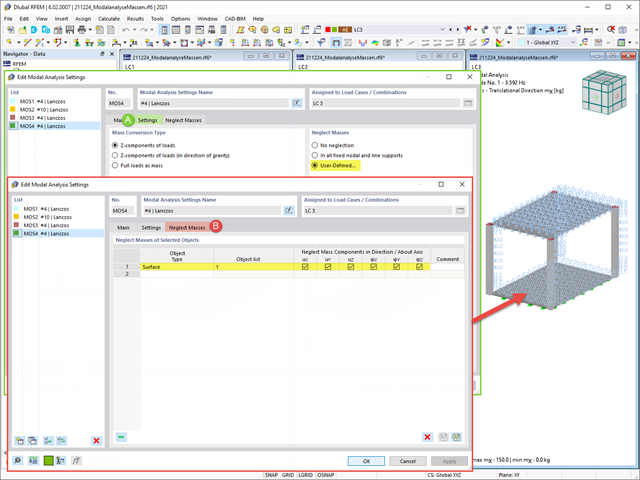
Często zachodzi potrzeba pominięcia mas. Dzieje się tak zwłaszcza w przypadku, gdy wyniki analizy modalnej mają być wykorzystane do analizy sejsmicznej. W tym celu wymagane jest 90% efektywnej masy modalnej w każdym kierunku. Pozwala to na pominięcie masy we wszystkich utwierdzonych podporach węzłowych i liniowych. Program automatycznie dezaktywuje powiązane masy.
Obiekty, których masy mają zostać pominięte w analizie modalnej, można również wybrać ręcznie. Dla lepszego widoku pokazaliśmy to ostatnie na rysunku. W wyniku wyboru przez użytkownika obiektów masowych wraz z skojarzonymi z nimi składowymi masowymi można pominąć masy.
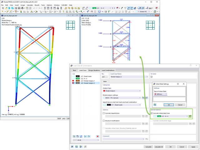
Podczas definiowania danych wejściowych dla przypadku obciążenia analizy modalnej można uwzględnić przypadek obciążenia, którego sztywności reprezentują początkową pozycję analizy modalnej. Jak to zrobić? Jak pokazano na rysunku, należy wybrać opcję "Uwzględnij stan początkowy z". Teraz otwórz okno dialogowe "Ustawienia stanu początkowego" i zdefiniuj typ Sztywność jako stan początkowy. W tym przypadku obciążenia, który jest stanem początkowym branym pod uwagę, można uwzględnić sztywność układu konstrukcyjnego, gdy pręty rozciągane ulegają uszkodzeniu. Celem tego wszystkiego: Sztywność z tego przypadku obciążenia jest uwzględniana w analizie modalnej. W ten sposób uzyskuje się wyraźnie elastyczny system.