156 Wyniki
Wyświetl wyniki:
Sortuj według:

- 002894
- Ogólne informacje
- Projektowanie konstrukcji aluminiowych RFEM 6
- Projektowanie konstrukcji aluminiowych RSTAB 9
W rozszerzeniu Projektowanie konstrukcji aluminiowych można uwzględnić lokalną redukcję wytrzymałości w strefie HAZ za pomocą spoin poprzecznych, w obliczeniach zgodnie z EN 1999-1-1.
Ponadto rozszerzenie Przekroje efektywne w RSECTION umożliwia obliczenie przekroju efektywnego z uwzględnieniem spoiny poprzecznej zgodnie z EN 1999-1-1.

- 002876
- Ogólne informacje
- Projektowanie konstrukcji betonowych RFEM 6
- Projektowanie konstrukcji betonowych RSTAB 9
W przypadku obliczeń betonu wyniki zbrojenia można wyświetlić w tabelach osobno w zależności od sytuacji obliczeniowych.

W rozszerzeniu Połączenia stalowe można używać nie tylko zwykłych typów prętów 'Belka', 'Kratownica' itd., ale także typu pręta 'Belka wynikowa' oraz przekroje z elementów powierzchniowych. Należy wybrać odpowiedni przekrój dla belki wynikowej, a następnie zdefiniować otwory prętowe w modelu powierzchniowym za pomocą edytora prętów.

Komponent 'Kontakt powierzchniowy' w rozszerzeniu Połączenia stalowe umożliwia uwzględnienie kontaktu ciśnieniowego między dwiema równoległymi płytami/płytami prętowymi. W takim przypadku można opcjonalnie uwzględnić tarcie między powierzchniami

W Centrum Dlubal dostępna jest obszerna biblioteka połączeń dla rozszerzenia Połączenia stalowe.
Dostęp do tej biblioteki można uzyskać bezpośrednio z rozszerzenia i przydzielić wstępnie zdefiniowane połączenia do odpowiednich węzłów. Połączenia zdefiniowane przez użytkownika można również zapisywać w bibliotece w Centrum Dlubal.

W rozszerzeniu Połączenia stalowe można teraz układać płyty w różne kształty geometryczne. Oprócz „Prostokąta” i „Okręgu” dostępny jest nowy kształt „Wielokąt”. Forma wielokąta jest określana przez zdefiniowaną współrzędną punktu.

W rozszerzeniu Połączenie stalowe można rozmieszczać obiekty w odniesieniu do innych obiektów.

Komponent "Stub" jest dostępny w rozszerzeniu Połączenia stalowe. Umożliwia ona wydłużenie pręta za pomocą połączenia płatwi z innym prętem (krótkiem) i połączenie go z komponentem odniesienia.

W rozszerzeniu Połączenia stalowe można zdefiniować kilka żeber jednocześnie na jednym pręcie lub płycie. Układ może być zdefiniowany według układu ortogonalnego lub biegunowego.

W rozszerzeniu Projektowanie konstrukcji betonowych dla programu RFEM 6 można przeprowadzić obliczenia odporności ogniowej ścian i płyt żelbetowych zgodnie z uproszczoną metodą tabelaryczną (EN 1992-1-2, rozdział 5.4.2 oraz tabele 5.8 i 5.9).

W rozszerzeniu Projektowanie konstrukcji betonowych można zdefiniować istniejące pionowe zbrojenie na ścinanie. Jest to następnie uwzględniane przy obliczaniu wytrzymałości na przebicie.

W konfiguracji granicznej dla wymiarowania połączenia stalowego istnieje możliwość modyfikacji granicznego odkształcenia plastycznego dla spoin.

Komponent "Płyta podstawy" umożliwia wymiarowanie połączeń z płytą podstawy za pomocą kotew zabetonowanych. Analizie poddawane są płyty, spoiny, zakotwienia oraz interakcja stal - beton.

- 002801
- Ogólne informacje
- Projektowanie konstrukcji betonowych RFEM 6
- Projektowanie konstrukcji betonowych RSTAB 9
Masz indywidualne przekroje słupów i ścian o różnej geometrii, które wymagają obliczenia nośności na przebicie?
Nie ma problemu. W programie RFEM 6 można przeprowadzić obliczenia na przebicie nie tylko dla przekrojów prostokątnych i okrągłych, ale także dla dowolnego kształtu przekroju.

Wynik obliczeń sejsmicznych jest podzielony na dwie sekcje: wymagania dotyczące prętów i połączeń.
"Wymagania sejsmiczne" zawierają Wymaganą wytrzymałość na zginanie i Wymaganą wytrzymałość na ścinanie połączenia belka-słup dla ram sprężystych. Są one wyszczególnione w zakładce 'Połączenia ram momentowych według prętów'. W przypadku ram stężonych w zakładce 'Połączenie stężone według pręta' podawana jest Wymagana wytrzymałość połączenia na rozciąganie oraz Wymagana wytrzymałość połączenia na ściskanie stężeń.
Przeprowadzone kontrole obliczeń są przedstawiane w tabelach. W szczegółach kontroli obliczeń w przejrzysty sposób przedstawione są wzory i odniesienia do normy.
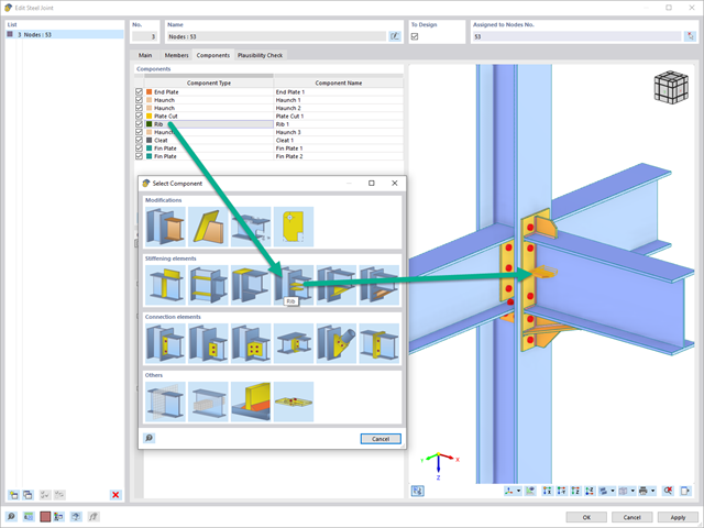
Za pomocą elementu "Żebro" można zdefiniować dowolną liczbę żeber podłużnych na blasze pręta. Wskazując obiekt odniesienia, można automatycznie określić na nim spoiny.
Komponent typu „żebro” może być również umieszczony na okrągłych profilach zamkniętych. Dafür wird zusätzlich die Vorgabe der Winkel zwischen den Rippen benötigt.

Teraz za pomocą kilku kliknięć można wstawiać blachy czołowe w połączeniach stalowych. Dane można wprowadzać za pomocą znanych typów definicji 'Offset' lub 'Wymiary i położenie'. Wprowadzając pręt odniesienia i płaszczyznę cięcia, można również pominąć część Przekrój pręta.
Za pomocą tego komponentu można łatwo modelować na przykład blachy czołowe na końcach słupa.

Rozszerzenie Analiza modalna umożliwia automatyczne zwiększanie poszukiwanych wartości własnych do momentu osiągnięcia zdefiniowanego współczynnika efektywnej masy modalnej. Uwzględniane są wszystkie kierunki translacyjne, które zostały aktywowane jako masy do analizy modalnej.
W ten sposób można łatwo obliczyć wymagane 90% efektywnej masy modalnej dla metody spektrum odpowiedzi.

- 002733
- Ogólne informacje
- Projektowanie konstrukcji stalowych RFEM 6
- Projektowanie konstrukcji stalowych RSTAB 9
Rozszerzenie Projektowanie konstrukcji stalowych umożliwia przeprowadzanie obliczeń sejsmicznych prętów stalowych zgodnie z AISC 341-16.
W tym celu dostępnych jest pięć typów systemów SFRS (Seismic Force-Resisting Systems).

W przypadku analizy spektrum odpowiedzi modeli budynków można wyświetlić współczynniki wrażliwości dla kierunków poziomych według kondygnacji.
Dzięki tym kluczowym wartościom można zinterpretować wrażliwość na efekty stateczności.

- 002720
- Ogólne informacje
- Analiza stateczności konstrukcji RFEM 6
- Analiza stateczności konstrukcji RSTAB 9
Stosując modalny współczynnik istotności (MRF) można ocenić, w jakim stopniu poszczególne elementy konstrukcyjne przyczyniają się do powstania rzeczywistego kształtu wyboczenia. Obliczenia opierają się na energii względnego odkształcenia sprężystego każdego pojedynczego pręta.
Dzięki MRF można rozróżnić lokalne i globalne kształty wyboczenia. Jeżeli kilka prętów ma znaczny MRF (np. > 20%), bardzo prawdopodobna jest niestateczność całej konstrukcji lub jej części. Jeżeli jednak suma wszystkich MRF dla kształtu drgań wynosi około 100%, należy spodziewać się lokalnego problemu ze statecznością (np. wyboczenia pojedynczego pręta).
Ponadto MRF może być wykorzystany do określenia obciążeń krytycznych i równoważnych długości wyboczeniowych poszczególnych prętów (np. do analizy stateczności). Kształty wyboczenia, dla których dany pręt ma małe wartości MRF (np. <20%), mogą zostać w tym kontekście pominięte.
MRF jest wyświetlany według kształtów wyboczenia w tabeli wyników w sekcji Analiza stateczności --> Wyniki według prętów --> Długości efektywne i obciążenia krytyczne.

Za pomocą komponentu "Cięcie płyty" można ciąć blachy (np. blachy węzłowe, blachy środnika itp.). Dostępne są różne metody cięcia:
- Płaszczyzna: Cięcie jest wykonywane na powierzchni najbliższej płycie odniesienia.
- Powierzchnia: Wycinane są tylko przecinające się części płyt.
- Bryła ograniczająca: Najbardziej zewnętrzny wymiar, szerokość i wysokość, jest wycinany jako prostokąt.
- Otoczka wypukła: Zewnętrzna otoczka przekroju służy do przycinania płyty. Jeżeli w węzłach narożnych przekroju występują zaokrąglenia, cięcie jest do nich dostosowywane.

- 002691
- Ogólne informacje
- Projektowanie konstrukcji betonowych RFEM 6
- Projektowanie konstrukcji betonowych RSTAB 9
W rozszerzeniu Projektowanie konstrukcji betonowych można przeprowadzić uproszczone obliczenia odporności ogniowej słupów (Rozdział 5.3.2) i belek (Rozdział 5.6), zgodnie z EN 1992-1-2.
W przypadku uproszczonych obliczeń odporności ogniowej dostępne są następujące metody weryfikacji:
- Słupy: Minimalne wymiary przekroju prostokątnego i okrągłego wg tabeli 5.2a oraz równania 5.7 do obliczania czasu ekspozycji pożarowej
- Belki: Minimalne wymiary i odległości między środkami zgodnie z Tabelą 5.5 i Tabelą 5.6
Siły wewnętrzne do obliczeń odporności ogniowej można wyznaczyć przy użyciu dwóch metod.
- 1: W tym przypadku siły wewnętrzne z wyjątkowej sytuacji obliczeniowej są bezpośrednio uwzględniane w obliczeniach.
- 2: Siły wewnętrzne z obliczeń w temperaturze normalnej są redukowane za pomocą współczynnika Eta,fi (ηfi) i są następnie wykorzystywane do obliczeń odporności ogniowej.
Ponadto istnieje możliwość modyfikacji rozstawu osi zgodnie z równ. 5.5.
.png?mw=640&hash=403c565ab80c4dd45c2d1356634fb74a90428b70)
W bibliotece konstrukcji warstwowych dostępni są następujący producenci drewna klejonego krzyżowo:
- Binderholz (USA)
- KLH (USA, CAN)
- Kalesnikoff (USA, CAN)
- Nordic Structures (USA, CAN)
- Mercer Mass Timber
- SmartLam
- Sterling Structural
- Konstrukcje nośne wymienione w Lignatec wydanie 32 "Drewno klejone krzyżowo z produkcji szwajcarskiej"
Wczytanie konstrukcji z biblioteki konstrukcji warstw powoduje automatyczne przejęcie wszystkich istotnych parametrów. Biblioteka jest stale aktualizowana.
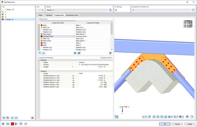
W rozszerzeniu Połączenie stalowe można użyć elementu "Bryła pomocnicza", aby dokładnie ciąć płyty i inne elementy konstrukcyjne. W ramach tego elementu, rolę obiektu pomocniczego mogą pełnić kształty takie jak sześcian, walec lub dowolny przekrój.
Przejdź do filmu
W rozszerzeniu Połączenia stalowe można łączyć profile zamknięte o przekroju okrągłym za pomocą spoin.
Profile okrągłe można łączyć ze sobą lub z płaskimi elementami konstrukcyjnymi. Spoiną można również łączyć pachwiny przekrojów znormalizowanych i cienkościennych.
Przejdź do filmu
Rozszerzenie Projektowanie konstrukcji betonowych umożliwia wymiarowanie prętów i powierzchni ze względu na zmęczenie zgodnie z EN 1992-1-1, rozdział 6.8.
W przypadku obliczeń zmęczenia można opcjonalnie wybrać dwie metody lub poziomy obliczeniowe w konfiguracjach obliczeniowych:
- Poziom obliczeniowy 1: Obliczenia uproszczone wg. do 6.8.6 i 6.8.7(2) Kryterium uproszczone jest stosowane dla częstych kombinacji oddziaływań zgodnie z EN 1992-1-1, rozdział 6.8.6 (2) oraz EN 1990, równ. (6.15b) wraz z obciążeniami od ruchu drogowego w stanie użytkowalności. Dla stali zbrojeniowej sprawdzany jest maksymalny zakres naprężeń zgodnie z 6.8.6. Naprężenie ściskające w betonie jest określane za pomocą górnego i dolnego dopuszczalnego naprężenia zgodnie z 6.8.7(2).
- Poziom analizy 2: Obliczanie równoważnego naprężenia niszczącego zgodnie z 6.8.5 i 6.8.7(1) (uproszczone obliczenia na zmęczenie): Obliczenia z wykorzystaniem zakresów równoważnych naprężeń niszczących są przeprowadzane dla kombinacji zmęczeniowych, zgodnie z EN 1992-1-1, rozdział 6.8.3, równ. (6.69) o specyficznie zdefiniowanym oddziaływaniu cyklicznym Qfat .

W rozszerzeniu Projektowanie konstrukcji betonowych można przeprowadzać obliczenia sejsmiczne dla prętów żelbetowych zgodnie z EC 8. Są to między innymi następujące funkcje:
- Konfiguracje obliczeń sejsmicznych
- Rozróżnianie klas ciągliwości DCL, DCM, DCH
- Możliwość przeniesienia współczynnika odpowiedzi z analizy dynamicznej
- Sprawdzenie wartości granicznej współczynnika odpowiedzi
- Weryfikacja nośności dla "Wytrzymały słup - słaba belka"
- Uszczegółowienie i reguły szczególne dla współczynnika ciągliwości krzywizny
- Uszczegółowienie i reguły szczególne dla ciągliwości lokalnej

W rozszerzeniu Projektowanie konstrukcji stalowych można przeprowadzić kontrolę obliczeń stateczności i przekrojów profili formowanych na zimno według EN 1993-1-3, zgodnie z punktami 6.1.2 - 6.1.5 i 6.1.8 - 6.1.10.
Przejdź do filmu
W rozszerzeniu Połączenia stalowe można klasyfikować sztywności połączeń.
Oprócz sztywności początkowej w tabeli wyświetlane są również wartości graniczne dla połączeń przegubowych i sztywnych dla wybranych sił wewnętrznych N, My i/lub Mz. Uzyskana klasyfikacja jest następnie wyświetlana w tabeli jako „przegubowa”, „półsztywna” i „sztywna”.
Przejdź do filmu