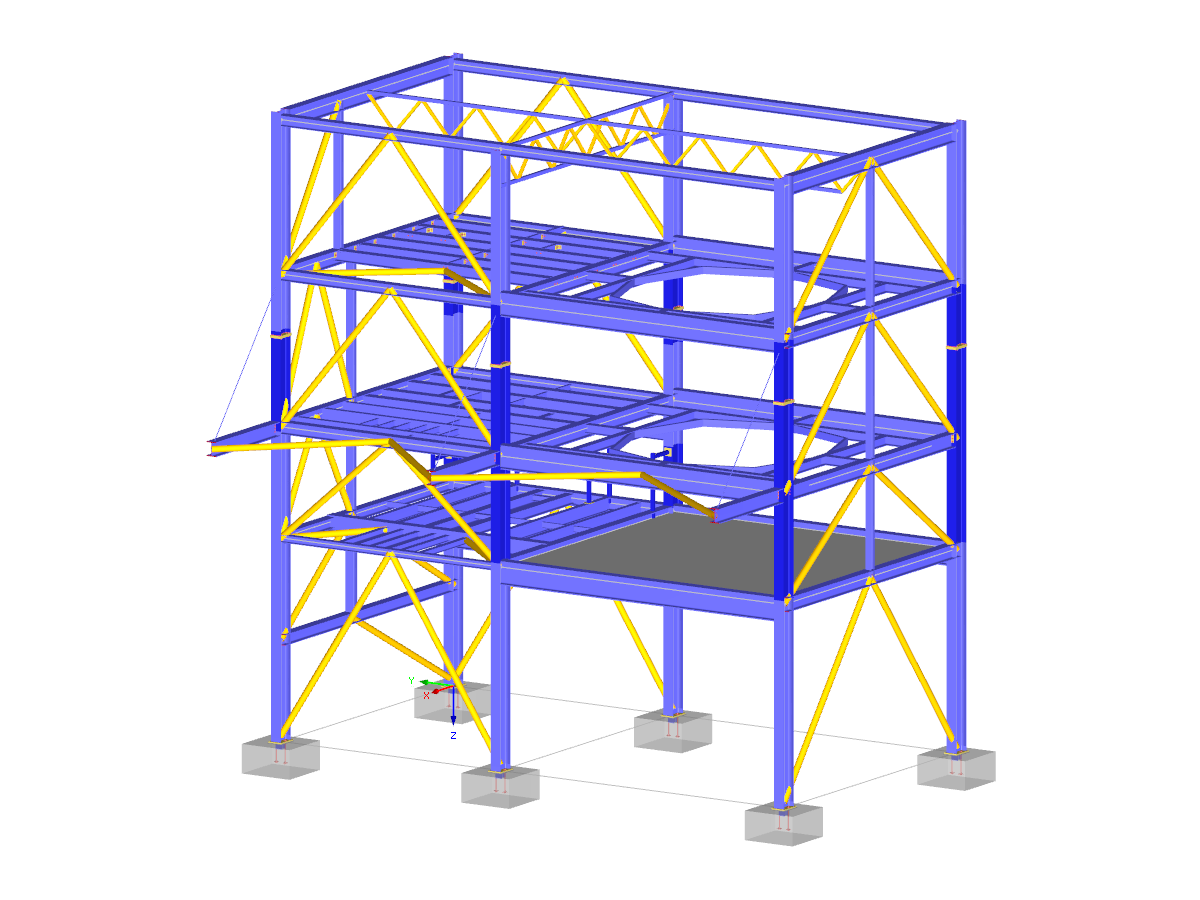
Steel hall with an integrated craneway and a reinforced concrete structure of an office complex
- Eurocode 5 | Timber Structures According to DIN EN 1995-1-1
- Eurocode 5 | Timber Structures According to EN 1995-1-1
- Eurocode 5 | Timber Structures According to DIN EN 1995-1-1
- Eurocode 5 | Timber structures according to EN 1995-1-1
- Eurocode 5 | Timber Structures According to DIN EN 1995-1-1
- Online Introductory Training RFEM - KTH Royal Institute of Technology
- Eurocode 5 | Timber Structures According to DIN EN 1995-1-1
- Free Eurocode 5 Training | Design of Timber Structures According to PN EN 1995-1-1
- Eurocode 5 | Timber Structures According to DIN EN 1995-1-1
- Steel Structures | RFEM 6 & RSTAB 9 by Dlubal Software
- Virtual Reality (VR) & Augmented Reality (AR) and Structural Models - Is That Possible?
Industrial Hall with Craneway Girder
Number of Nodes | 342 |
Number of Lines | 543 |
Number of Members | 455 |
Number of Surfaces | 9 |
Number of Load Cases | 76 |
Number of Load Combinations | 139 |
Number of Result Combinations | 9 |
Total Weight | 147.000 tons |
Dimensions | 68.24 x 84.65 x 29.78 feet |
Program Version | 5.25.01 |
You can download this structural model to use it for training purposes or for your projects. However, we do not assume any guarantee or liability for the accuracy or completeness of the model.
The fatigue strength design is based on the analysis using damage equivalent factors. The damage equivalent stress ranges ΔσE,2 and ΔτE,2 related to 2*106 stress cycles have to be compared to the limit values of the fatigue strength ΔσC or ΔτC for 2*106 stress cycles of the corresponding detail, taking into account the partial safety factors.
In this way, the individual design requirements are specified. Separate design cases enable flexible analysis of selected members, sets of members, and actions, as well as of individual cross‑sections. Design-relevant parameters such as B. selecting the design concept as well as partial safety factors can be defined freely.
In the "Edit Section" dialog box, you can display the buckling shapes of the Finite Strip Method (FSM) as a 3D graphic.
Do you have individual column sections and angled wall geometries, and need punching shear design for them?
No problem. In RFEM 6, you can perform punching shear design not only for rectangular and circular sections, but for any cross-section shape.
- Design of five types of seismic force-resisting systems (SFRS) includes Special Moment Frame (SMF), Intermediate Moment Frame (IMF), Ordinary Moment Frame (OMF), Ordinary Concentrically Braced Frame (OCBF), and Special Concentrically Braced Frame (SCBF)
- Ductility check of the width-to thickness ratios for webs and flanges
- Calculation of the required strength and stiffness for stability bracing of beams
- Calculation of the maximum spacing for stability bracing of beams
- Calculation of the required strength at hinge locations for stability bracing of beams
- Calculation of the column required strength with the option to neglect all bending moments, shear, and torsion for overstrength limit state
- Design check of column and brace slenderness ratios