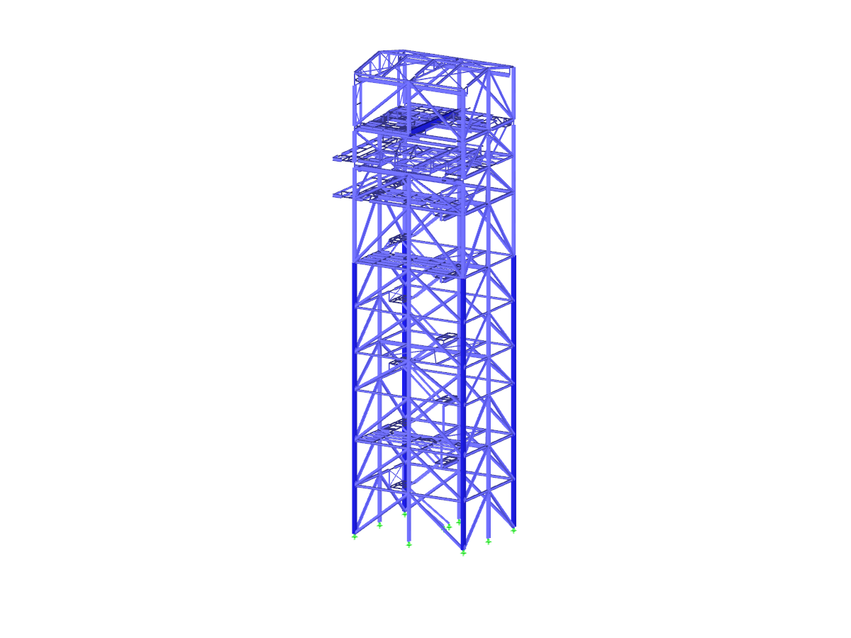
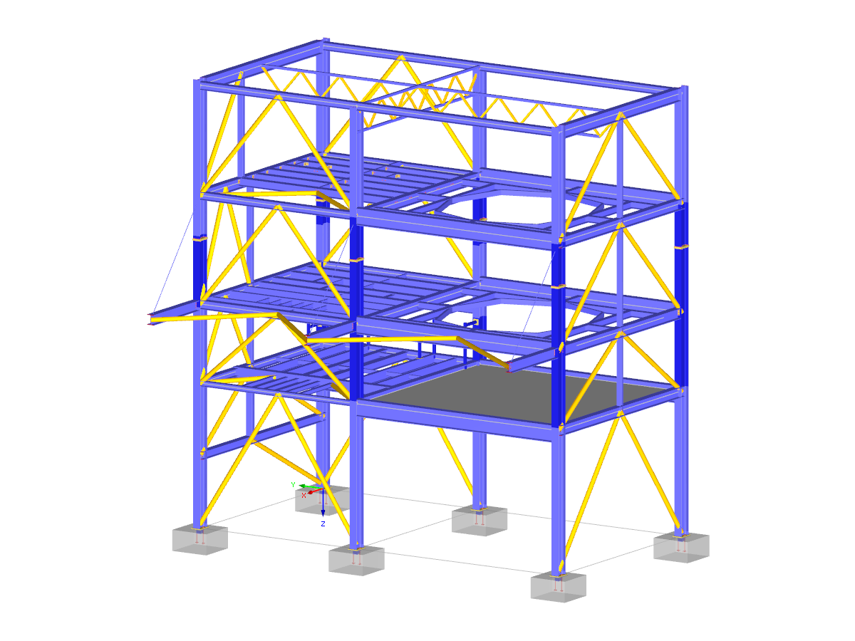
- Camera Fly Mode
- Create 3D glTF Models (*.glb and *.glTF Formats)
- Dlubal RFEM 5 | Introduction to Structural FEA Software
- Connections in Steel Structures | Dlubal Software
- Structural Analysis & Design of Steel Structures | Dlubal Software
- Structural Analysis and Design Software for Steel Structures | RFEM 6 & RSTAB 9 by Dlubal Software
- SVT 017 | Camera Fly Mode
- Dlubal Software | Enjoy Structural Analysis...
- UPD 002 | Program Version Update x.24
- Top 5 Reasons for Dlubal Software
- Merry Christmas 2020
Steel Tower Structure
Number of Nodes | 638 |
Number of Lines | 943 |
Number of Members | 927 |
Number of Surfaces | 2 |
Number of Load Cases | 15 |
Number of Load Combinations | 131 |
Number of Result Combinations | 7 |
Total Weight | 256.050 tons |
Dimensions | 67.42 x 82.68 x 56.76 feet |
Program Version | 5.22.01 |
With the Camera Fly Mode view option, you can fly through your RFEM and RSTAB structure. Control the direction and speed of the flight with your keyboard. Additionally, you can save the flight through your structure as a video.
In the "Edit Section" dialog box, you can display the buckling shapes of the Finite Strip Method (FSM) as a 3D graphic.
- Design of five types of seismic force-resisting systems (SFRS) includes Special Moment Frame (SMF), Intermediate Moment Frame (IMF), Ordinary Moment Frame (OMF), Ordinary Concentrically Braced Frame (OCBF), and Special Concentrically Braced Frame (SCBF)
- Ductility check of the width-to thickness ratios for webs and flanges
- Calculation of the required strength and stiffness for stability bracing of beams
- Calculation of the maximum spacing for stability bracing of beams
- Calculation of the required strength at hinge locations for stability bracing of beams
- Calculation of the column required strength with the option to neglect all bending moments, shear, and torsion for overstrength limit state
- Design check of column and brace slenderness ratios
The seismic design result is categorized into two sections: member requirements and connection requirements.
The "Seismic Requirements" include the Required Flexural Strength and the Required Shear Strength of the beam-to-column connection for moment frames. They are listed in the ‘Moment Frame Connection by Member’ tab. For braced frames, the Required Connection Tensile Strength and the Required Connection Compressive Strength of the brace are listed in the ‘Brace Connection by Member’ tab.
The program provides the performed design checks in tables. The design check details clearly display the formulas and references to the standard.