Description
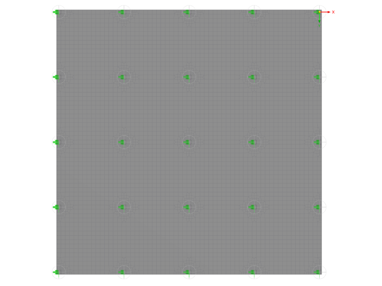
The model is based on the example 4 of [1]: Point-supported slab. The internal forces and the required longitudinal reinforcement can be found the in verification example 1022. In this example, punching is examined in the axis B/2.
The required punching shear reinforcement is determined with manual calculation. Then, the results are compared with the RFEM results.
Analytical Solution
The middle effective depth deff results from the concrete cover and the diameter of the longitudinal reinforcement:
The basic control perimeter u1 is then calculated:
With the coefficient ß=1.10, a shear force to be supported in the control perimeter is calculated:
The punching shear resistance of the slab without shear reinforcement:
Punching shear reinforcement is therefore necessary.
Maximum value of punching shear resistance:
Determination of the punching shear reinforced area:
distance from the outer perimeter to the edge of the load surface:
The required number of shear reinforcement rows:
With 3 rows of reinforcement, the radial spacing sr is:
Reinforcement per row:
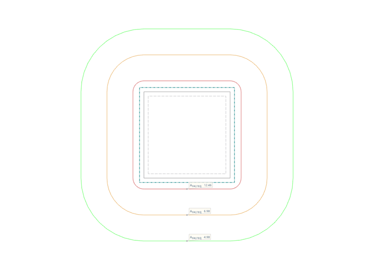
This results in the following punching shear reinforcement in the individual reinforcement rows:
| Reinforcement row | Distance from column edge | Factor ksw | Punching shear reinforcement |
| Asw*ksw | |||
| 1 | 0.5d=0.095 m | 2.5 | 2.5*4.98cm2=12.45cm2 |
| 2 | 0.085+0.99=0.194 m | 1.4 | 1.4*4.98cm2=6.97cm2 |
| 3 | 0.085+2*0.99=0.293 m | 1.0 | 1.0*4.98cm2=4.98cm2 |
Results
In the following tables, the results of RFEM 6 are compared with the analytical solution.
| Punching shear design | |||||
| Designation | Variable | Unit | RFEM result | Analytical solution | Ratio |
| Design shear force | VEd | [kN] | 787.3 | 787.3 | 1.0 |
| Basic control perimeter | u1 | [m] | 4.188 | 4.188 | 1.0 |
| Maximum shear stress | vEd | [MN/m2] | 1.088 | 1.088 | 1.0 |
| Punching shear resistance without shear reinforcement | vRd,c | [MN/m2] | 0.929 | 0.929 | 1.0 |
| Maximum value of punching shear resistance | vRd,max | [MN/m2] | 1.300 | 1.300 | 1.0 |
| Outer perimeter | uout | [m] | 5.889 | 5.889 | 1.0 |
| Distance from the outer perimeter to the edge of the load surface | aout | [m] | 0.651 | 0.651 | 1.0 |
| Required number of shear reinforcement rows | n | [-] | 3 | 3 | 1.0 |
| Punching shear resistance with shear reinforcement | Asw | [cm2] | 4.98 | 4.98 | 1.0 |
| First reinforcement row | Asw,1 | [cm2] | 12.46 | 12.45 | 1.0 |
| Distance from the outer perimeter to the edge of the load surface | lsw,1 | [m] | 0.095 | 0.095 | 1.0 |
| Second reinforcement row | Asw,2 | [cm2] | 6.98 | 6.97 | 1.0 |
| Distance from the outer perimeter to the edge of the load surface | lsw,2 | [m] | 0.194 | 0.194 | 1.0 |
| Third reinforcement row | Asw,3 | [cm2] | 4.98 | 4.98 | 1.0 |
| Distance from the outer perimeter to the edge of the load surface | lsw,3 | [m] | 0.293 | 0.293 | 1.0 |