Mechanical Displacement System Design, Saint-Martin-de-la-Porte, France
Customer Project
-
01
Rail System with Sigma-X Stresses (© AGICEA)
-
01
Rail System with Components (© AGICEA)
-
01
Bracket Connection and Roller Von Mises Stresses (© AGICEA)
-
01
Rail System with Sigma-X Stresses (© AGICEA)
-
01
Mechanical Displacement System Design, Saint-Martin-de-la-Porte, France
-
01
Mechanical Displacement System Image (© AGICEA)
-
02
Rail System with Components (© AGICEA)
-
02
Rail System with Sigma-X Stresses (© AGICEA)
-
02
Bracket Connection and Roller Von Mises Stresses (© AGICEA)
-
02
Rail System with Sigma-X Stresses (© AGICEA)
-
02
Mechanical Displacement System Design, Saint-Martin-de-la-Porte, France
-
02
Mechanical Displacement System Image (© AGICEA)
-
03
Bracket Connection and Roller Von Mises Stresses (© AGICEA)
-
03
Rail System with Sigma-X Stresses (© AGICEA)
-
03
Rail System with Components (© AGICEA)
-
03
Rail System with Sigma-X Stresses (© AGICEA)
-
03
Mechanical Displacement System Design, Saint-Martin-de-la-Porte, France
-
03
Mechanical Displacement System Image (© AGICEA)
-
04
Mechanical Displacement System Image (© AGICEA)
-
04
Rail System with Sigma-X Stresses (© AGICEA)
-
04
Rail System with Components (© AGICEA)
-
04
Bracket Connection and Roller Von Mises Stresses (© AGICEA)
-
04
Rail System with Sigma-X Stresses (© AGICEA)
-
04
Mechanical Displacement System Design, Saint-Martin-de-la-Porte, France
The goal of the hydroelectric power plant project was to analyze the resistance of a double mechanical displacement system on rails subjected to tensile stress.
Structural Analysis |
AGICEA, Orange, France www.agicea-bureau-etudes.fr |
Investor |
Groupe MOSCATELLI, Sorgues, France www.groupe-moscatelli.com |
Model
Technical Details and Calculation
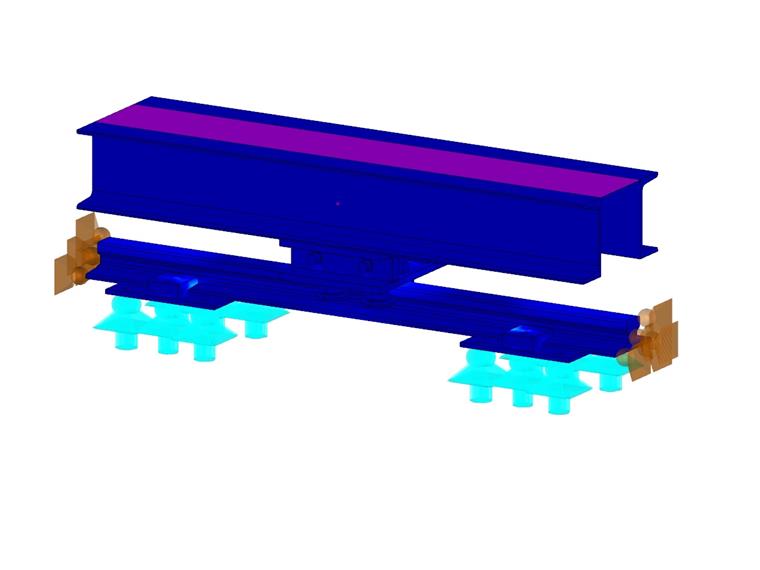
The model includes various solids with different materials (steel S235, S275, bronze, steel 42CD4). The rail is supported by clamping connections fixed on foundation plates. The entire system can be moved, with the four rollers fixed on a slide component and limited to displacement in the X- and Y-directions. The entire frame structure is represented by double UPN sections.
Since no tension force was specifically defined, the model was calculated with an iterative method taking into consideration the Eurocode safety factor until the stability and elastic limit of each material was reached.
The decision was made to calculate each component as a solid model (3D FEA) to check each mesh point as well as whether the contact stresses and internal deformations would affect the behavior of the respective part. Additionally, the mesh was considerably refined.
Result Evaluation
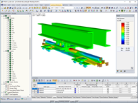
After the calculation, the deformation was checked to ensure realistic results.
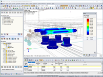
Then, each component was isolated from similar material elements to view the maximum von Mises stresses. Figure 03 displays the clamping connection and roller von Mises stresses.
The iterative calculations were completed until the stability or elastic limit of the material was reached to derive the maximum allowable tensile force in the system. This maximum allowable load was determined to be 1.41 tons.
In addition, the project calculation package has been published where all results, input data, and design checks can be reviewed.
Keywords
Dlubal Software Agicea RFEM Mechanical translation Rail Tension force Deformation
Write Comment...
Write Comment...
Contact Us
Do you have further questions or need advice? Contact us via phone, email, chat, or forum, or search the FAQ page, available 24/7.

Parameterized FE Model for Designing Rigid End Plate Joints
Designing rigid end plate connections is difficult for four-row connection geometries and multi-axis bending stresses, because there are no official design methods.
Programs Used for Structural Analysis