


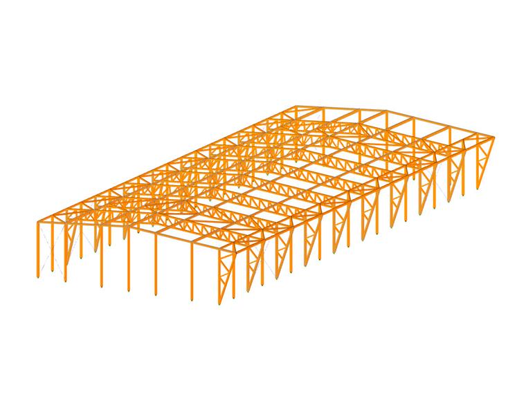
It is a building with a free span of 26.5 m (86.94 ft) and 60 m (196.85 ft) in length between the pillars, designed by repeating double hinged frames made completely of timber, with a distance of 6.20 m (20.34 ft) between the frames. The free height in the lowest area, which coincides with the sides with the pillars, is 6 meters (19.68 ft).
Furthermore, the building has a lateral cantilever with a length of 7 m (22.97 ft) in continuity with each frame, the purpose of which is to obtain an exterior storage area and space for the air extraction systems for the industrial equipment that will be installed inside.
Structural Design
The design has sought to combine different requirements:
- The structure should be built with commercially conventional structural timber members; that is, pieces of a length not exceeding 13.5 m (44.29 ft), so that they can be transported in conventional trucks. Furthermore, it should have a reduced square alignment (height x width), as is commercially standard.
- Reducing the need for timber per m² built. No large square elements have been used.
- The covering support also requires the lowest ratio of m3 of timber covering to m² of the roof. A high-profile metal cover has been used to reduce the number of purlins.
- The structure should be made completely of timber. This assumes greater complexity, since the pillars are also made of timber, which requires careful analysis and treatment of the local stability of each frame as well as the global stability of the structure.
| Location | Maderas Besteiro Carretera Friol, km. 1, 27004 Lugo Spain |
| Design, Structural Analysis, Manufacturing, and Assembly | Maderas Besteiro |


