
Question:
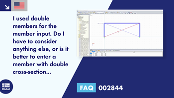
I used double members for the member input. Do I have to consider anything else, or is it better to enter a member with double cross-section properties?
Answer:
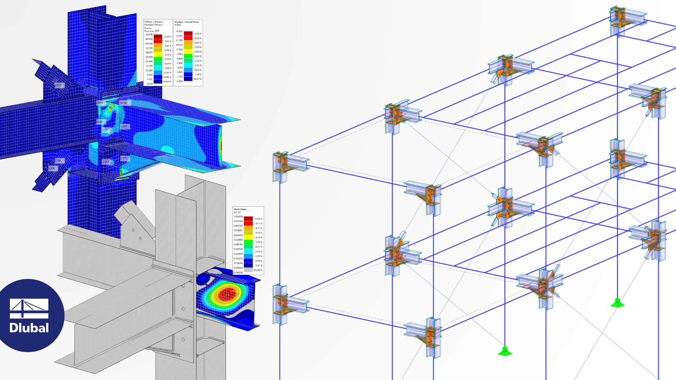
For the design of multi-part components, you can use the combined cross-sections of the cross-section library. The cross-section properties are automatically calculated from the individual cross-sections and then taken into account for the design in the add-on modules. A flexible connection of lattice members is modeled by entering an equivalent plate thickness t*.
If you have edited the cross-section values or the stiffnesses of a member using the "Modify stiffness" function, these are generally not used in the design modules. The modified stiffnesses are only used for the calculation of internal forces.
The design checks in RF‑/STEEL EC3 also require the exact dimensions and the cross-section shape to perform the c/t design or to select the interaction equation, for example. The effect of the stiffness modification on these individual parameters is not explicit for all cases, and thus cannot be used in the add-on module.


.png?mw=350&hash=b2324c4db119938012b5490afaa56e9aa826cdcc)


.png?mw=600&hash=49b6a289915d28aa461360f7308b092631b1446e)


