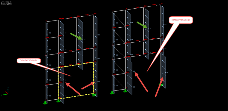
In both cases shown in Image 01, a load of 51 kN is applied in the global X‑direction. The problem is the different distributions in both cases:
In Variant A, the green loads are larger and the red ones are smaller, and in Variant B, it is the other way around. The biggest problem in Variant A is that the red loads are strangely the same as in the area above, where there are still intermediate members (green load).
The problem here is the area outlined in yellow. Internally, the load of the entire surface is calculated first (51 kN), and then the closed cells (a plane that is completely framed by members) are subtracted from it.
Since the surface framed in yellow is not a cell (the limiting member between Node 20 and Node 36 is missing), this is a special case. The load generator proceeds as follows:
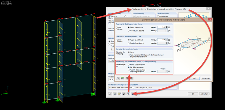
By subtracting the horizontal members, a large notional cell is created between nodes 23, 760, 36, and 20. Due to the aforementioned missing cell, it is assumed that all outer members have a constant load (1.6 and 1.0 kN/m) and the remaining load is distributed to the inner members. Thus, in Variant A, the green load is higher and the red loads are smaller. To modify this distribution, the "Use All Members" option is available in the load generator, as shown in Image 02.
This option allows you to generate the missing cell internally and to distribute the loads according to Variant B. In our Knowledge Base, you can find an interesting article about this: