


![Vibration Analysis (Source: [3])](/en/webimage/009798/467822/01-de-png.png)
For biaxial plate structures as well, such as cross‑laminated timber plates, the design is usually performed on a uniaxial equivalent member. To explain the theoretical background, we will analyze a member first.
Example: Beam Structure
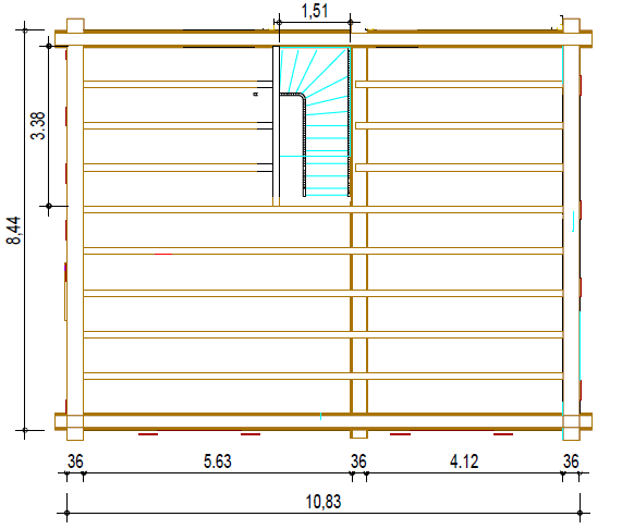
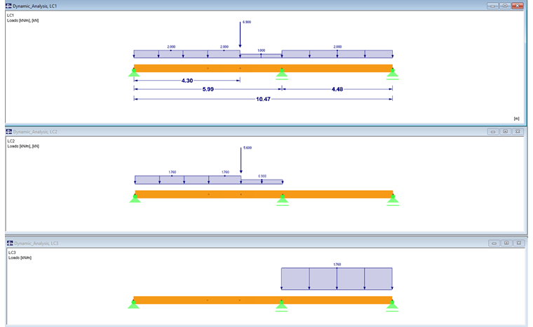
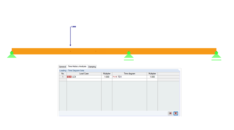
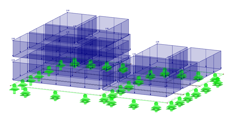
The advantages and disadvantages of member and surface design are explained on a practical structural component. The ground plan of a building has the dimensions of 8.44 m x 10.83 m. At 5.99 m in the longitudinal direction of the building, there is a structural interior wall. As you can see in Image 02, a timber beam floor was initially created and analyzed in the RX‑TIMBER Continuous Beam program. In addition to the uniform loads displayed in Image 03, a concentrated load results from the transition at the end of the staircase well.
LC1 = 6.9 kN
LC2 = 5.6 kN
The calculation performed in RX-TIMBER DLT gives the result of the required cross-section of 14/32 cm.
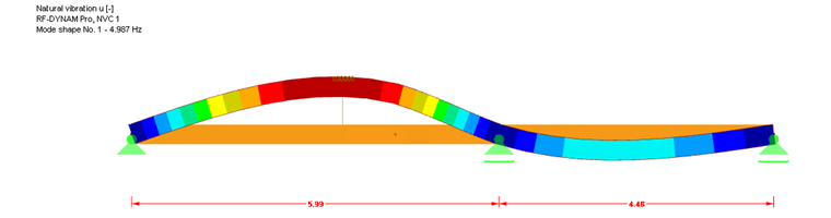
The simplified vibration design in RF‑TIMBER Pro, with the load combination of LC1 + LC2, gives the maximum deformation of 19.4 mm. The two-span beam can be converted into a fixed single-span beam, so the following limiting values of the deformation are available. The vibrations are thus kept mathematically over a value of 8.0 Hz. Find more information in [3].
A cross‑section of 14/62 cm would be required to comply with the simplified vibration design in RF‑TIMBER Pro.
You can perform more precise design checks in RF‑DYNAM Pro – Natural Vibrations and RF‑DYNAM Pro – Forced Vibrations, taking into account the requirements mentioned in [3].
![Flowchart from [3]](/en/webimage/009802/2420470/05-en-png-png.png)
First, the detailed analysis checks whether the natural frequency is f0 ≤ fmin.
fmin = 4.5 Hz > f0 = 4.4 Hz
Thus, the limitation is not met.
The next step is to investigate whether the acceleration a ≤ alimit. For this, the periodic function of 2 Hz is defined in RF-DYNAM Pro – Forced Vibrations. Converted to ω with 2Hz ∙ 2π = 12.566 rad/s. According to [3], Section 2.2.4, the acting force variable in time and location with Fdyn = 0.4 F(t) applies.
The definition of a periodic function does not reflect the requirements from [3] and represents a simplification. The correct representation of walking on a slab is explained in the following webinar (in German only):

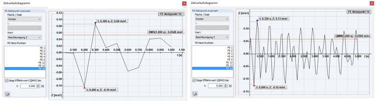
In the next step, a load case is defined with the concentrated load of 1 kN (maintenance load), which is selected for design in RF-DYNAM Pro – Forced Vibrations. The concentrated load is defined on the location of the selected maximum eigenvalue. According to [1], Lehr's damping of ξ = 0.01 is used. The acceleration extends with 2 Hz over 5 seconds. The root mean square (see Image 10) is calculated as 0.05 m/s².

alimit = 0.1 m/s > a = 0.05 m/s²
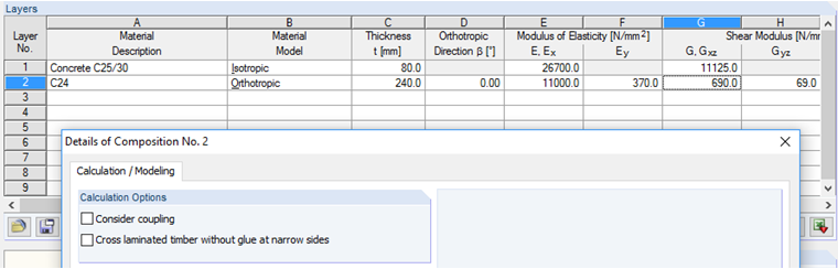
Thus, the analysis for the root mean square has been done. However, it results in a slight exceedance of 0.1 m/s². According to [3], it is possible to consider a screed as an additional stiffness and mass in the calculation. The cross-section is defined under the composite cross-sections in RFEM. The connection between the screed and the timber cross-section transfers no stiffnesses in this case (connection without shear). Structural height of the screed is set to 8 cm. More information about the composite cross-sections is available in the manual of RF-TIMBER Pro.

Example: Plate Structure
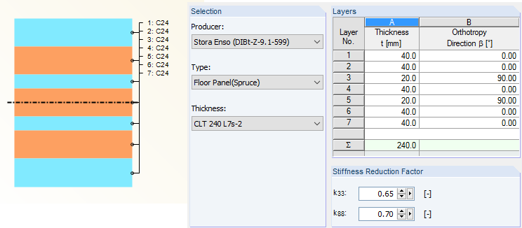
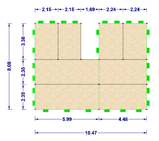
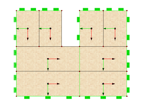
The example of the ground plan shown in Image 02 is converted to a cross‑laminated timber plate with the cross‑section CLT 240 L7a‑2 (according to [2]). The panels in the lower part are defined in the same way as the beam structure: the continuous beam has the total length of 10.47 m, and the span width of 5.99 m (Span 1) and 4.48 m (Span 2) is defined. The plates with the length of 3.38 m are connected to continuous plates (see Image 13).
The connection rigidity of the plates is not considered in this case, since it is assumed that the shorter plates are placed on the continuous plates, so there is no rigidity. A line hinge with the degree of freedom φx = 0 kNm/rad/m is only defined for the rotation at all plate edges. The stress direction of the plates is illustrated in Image 14.
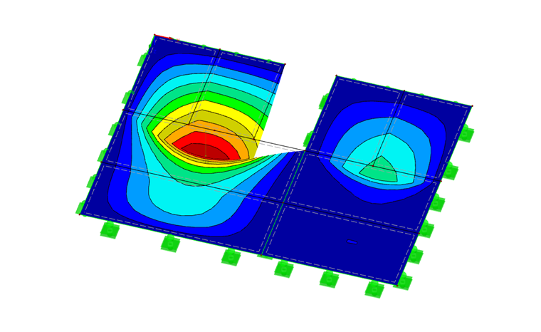
The design is performed in RF-LAMINATE and the calculated stiffnesses result in a deformation of 21.4 mm in the characteristic/quasi-permanent combination. Also in this case, the simplified vibration design is exceeded. Therefore, the procedure of the previous chapter will be repeated for the plate structure.
The design process in RF-LAMINATE is explained in the manual.
In order to achieve a more precise calculation of the plate structure in RF-DYNAM Pro – Natural Vibrations and RF-DYNAM Pro – Forced Vibrations, a combination with LC1 + LC2 is created again.
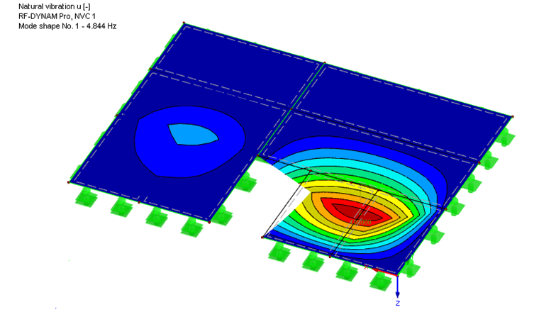
The result of the calculation with this combination in RF‑DYNAM Pro – Natural Vibrations is the natural vibration of 4.8 Hz. In the case of the first mode shape of the plate structure, the maximum failure mode also results in the mid‑span of the first panel.
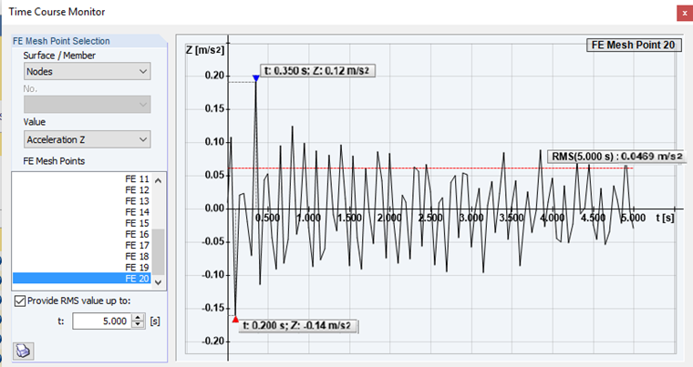
Also in this case, the concentrated load of 1 kN is defined and superimposed with the same function as in the case of the member structure. Image 18 shows the root mean square of 0.0469 m/s² at 5 seconds. Even the maximum acceleration is almost within the limit criterion of alimit ≤ 0.1 m/s². The limit value is slightly exceeded with 0.12 m/s². For further analysis, the stiffness and mass of the cross-section will be increased by a screed with a thickness of 8 cm in RF-LAMINATE. For this, the stiffness of the cross-laminated timber plate is represented by an equivalent orthotropic timber cross-section.
The stiffness matrix of this composite cross-section is determined without considering the shear coupling between the screed and the cross-laminated timber plate.
Using this method, we finally succeeded in achieving the maximum value of the acceleration below the limit criterion, as you can see in Image 20.

Conclusion
The biaxial design of a structural component allows you to reduce a cross‑section from 64 cm to 22 cm of thickness of a cross‑laminated timber plate while the vibration design according to Eurocode 5 is fulfilled.