Section 12.8.6 [1] gives the following equation to calculate the entire story drift:
|
δx |
Total displacement of a story [in (mm)] |
|
Cd |
Magnification factor of deflection according to Table 12.2-1 |
|
δxe |
Displacement at the required location, determined in the elastic analysis [in (mm)] |
|
Ie |
Importance factor specified in Section 11.5.1 |
The mutual story drift δ is the difference of the total displacement at the top and bottom of the story. It has to be determined in the corresponding centers of gravity. If the building is classified as Class C or worse, or if horizontal irregularities are present, the greatest difference of two vertically oriented points at the top and bottom of the considered story along a corner has to be determined. The following example shows the determination of the story drift in RFEM.
Entering the Response Spectrum in RF-DYNAM Pro
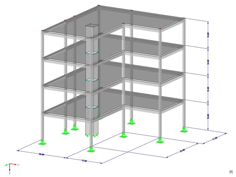
To gain an insight into this topic, the three-story building shown in Image 01 is used with an L-shaped ground plan. Three load cases will be defined: self-weight, live loads, and snow loads. The front view of the building is continuous.
A natural vibration analysis has to be performed first, to be able to generate the response spectrum. Only the masses in both horizontal directions are considered in this example. The masses are combined according to ASCE 7-16, Section 12.7.2 [1].
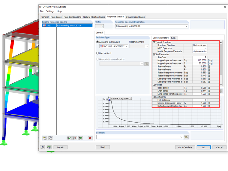
There is the possibility to create the response spectrum according to an implemented standard or to import a user-defined response spectrum. For this example, the response spectrum is generated according to the implemented standard ASCE 7-16. Thus, it is possible to include the parameters Cd and Ie when creating the response spectrum and to consider them in the story drift calculation.
The method with structural equivalent loads will be used for the calculation that is based on the multi-modal response spectrum analysis. It is important here to consider at least 90% of the effective mass. Mode shapes that activate no or little mass can be excluded from the calculation in the "Dynamic Load Cases - Mode Shapes" tab. After the calculation, the load cases and the resulting result combinations are generated separately for each direction.
Determining Story Drift in RFEM
To evaluate the story drift, it is necessary first to create the center of gravity for each story as a node. Using the "Center of Gravity and Info" shortcut menu, it is possible to determine the center of gravity and to generate a node in this point. The position of the center of gravity is shown in the following image. Since the story drift has to be determined always at the top and bottom edges of the story, the node of the center of gravity should be shifted to the plane of the ceiling.
![Position of Center of Gravity in [ft]](/en/webimage/009089/2713907/03-de.jpg?mw=760&hash=f4e2df58b66f20aa87acc1392441f0a0db697977)
When determining story drift, an important point must be considered: The difference of the displacements must not be determined from the results already superimposed by square addition, but may be superimposed only after the difference formation. Thus, the following formula applies:
Due to this condition, the result combination created by the add-on module cannot be used for the evaluation. Instead, the story drift must be evaluated for each mode shape individually for each direction, then superimposed manually.
In this example, the story drift is considered only in the center of gravity. By displaying the displacement ux with a user-defined view in the centers of gravity per story, you can determine the story drift from the differences of superimposed points.
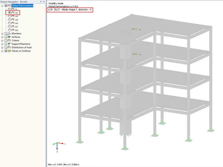
The following shows the procedure for the top floor as an example. The results of the individual mode shapes are listed in the table below:
| Mode 1 | Mode 2 | Mode 3 | Mode 4 | Mode 6 | Mode 8 | Mode 9 | Mode 10 | |
|---|---|---|---|---|---|---|---|---|
| ux in node 46 | -1.083 in. | -0.198 in. | -1.038 in. | 0.037 in. | 0.005 in. | 0.024 in. | 0.000 in. | -0.001 in. |
| ux in node 47 | -0.913 in. | -0.145 in. | -0.692 in. | -0.007 in. | -0.002 in. | -0.010 in. | 0.001 in. | 0.003 in. |
| δx | -0.170 in. | -0.053 in. | -0.346 in. | 0.044 in. | 0.007 in. | 0.034 in. | -0.001 in. | -0.004 in. |
| Mode 1 | Mode 2 | Mode 3 | Mode 4 | Mode 6 | Mode 8 | Mode 9 | Mode 10 | |
|---|---|---|---|---|---|---|---|---|
| uy in node 46 | -0.126 in. | -2.028 in. | -0.091 in. | 0.004 in. | 0.047 in. | 0.002 in. | -0.003 in. | 0.000 in. |
| uy in node 47 | -0.105 in. | -1.464 in. | -0.060 in. | -0.001 in. | -0.023 in. | -0.001 in. | 0.005 in. | 0.001 in. |
| δy | -0.021 in. | -0.564 in. | -0.031 in. | 0.005 in. | 0.070 in. | 0.003 in. | -0.008 in. | -0.001 in. |
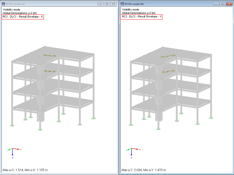
This procedure has to be carried out for each story; this way, the maximum story drift for the entire building can be determined. If you compare the calculated story drifts with those in the automatically created result combinations, the difference becomes clear. Thus, it is proven that first the difference of the drifts may be superimposed by square addition, otherwise the story drift will be underestimated.